AirPick - Instruction Manual
l
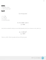
S= 4 (recommended)
l
µ = 0.5
Validation that F
p
> F
c
: 305.6 N > 97.7N
Since 305.6 N > 97.7 N , the rule is respected and we can ensure the good grip of the part.
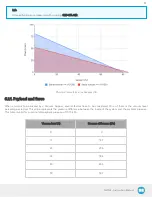
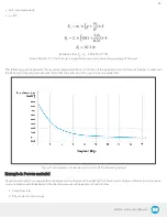
The following graph represents the recommended acceleration in function of the payload when the Vacuum Gripper is used with
the Robotiq brackets and accessories. Note that the optimal suction cup choice is represented.
Fig. 6-11: Acceleration of the robot in function of the Vacuum payload
Example 2: Porous material
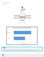
For porous material, non-negligible air leakages can be observed. Considering that, the Vacuum Gripper will work in a continuous
mode to compensate leakages and the reached vacuum will depend on 4 main factors:
1. Pump flow rate
2. The model of suction cups
85
Содержание AirPick
Страница 25: ...Fig 3 7 Mounting air nodes suction cups air bolts air nuts on the bracket 25...
Страница 27: ...Fig 3 9 Robotiq Vacuum Gripper with pigtail cable and device cable wiring scheme 27...
Страница 35: ...Fig 4 1 Vacuum Gripper control logic overview 35...
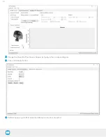
Страница 57: ...7 Click on the New Project icon in the upper left corner of the screen 57...
Страница 58: ...AirPick Instruction Manual 8 Enter a name for your program and click on the OK button 9 58...
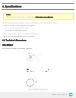
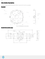
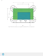
Страница 76: ...Fig 6 5 Minimum and maximum arrangement possibilities of the air nodes position 76...
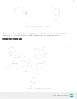
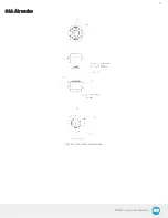
Страница 77: ...AirPick Instruction Manual 6 1 3 Air nodes Fig 6 6 Air nodes dimensions 77...
Страница 103: ...AirPick Instruction Manual 12 Appendix Fig 12 1 Pneumatic schema of the AirPick Vacuum Gripper...

