


AirPick - Instruction Manual
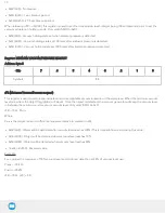
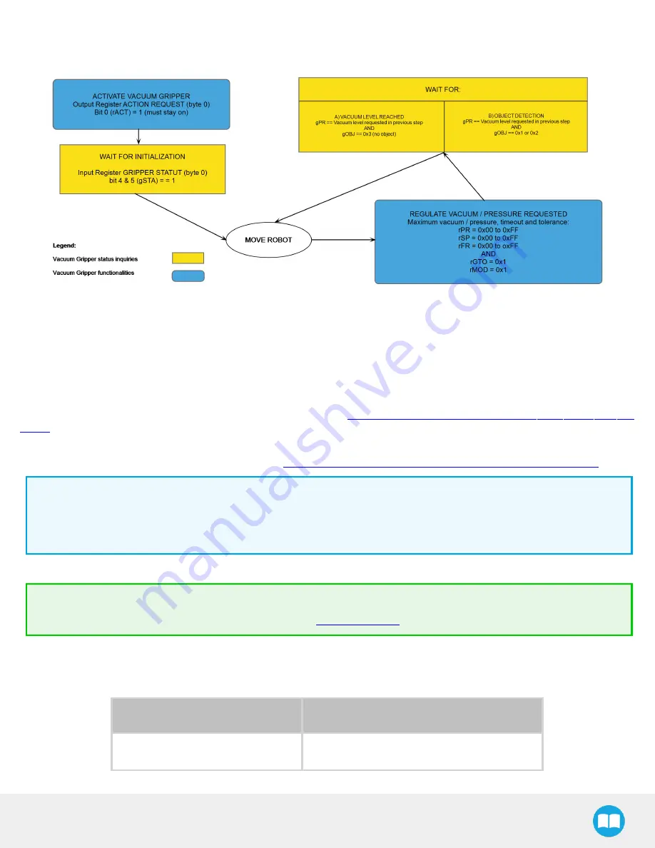
4.6. Control logic
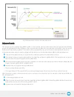
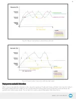
Fig. 4-5: Example of the Vacuum Gripper control logic with associated registers.
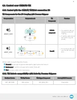
4.7. Modbus RTU communication
The Vacuum Gripper can be controlled by Modbus RTU over RS485. This section is intended to provide guidelines for setting up a
Modbus master that will adequately communicate with the Gripper.
For a general introduction to Modbus RTU and for details regarding the CRC algorithm, the reader is invited to read the Modbus
over serial line specification and implementation guide available at:
http://www.modbus.org/docs/Modbus_over_serial_line_V1_
Scanner from Chipkin Automation Systems available at:
http://www.store.chipkin.com/products/tools/cas-modbus-scanner
Modbus RTU specifications and details can be found at
4.7.1. Connection setup
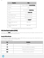
The following table describes the connection requirements for controlling the Gripper using the Modbus RTU protocol.
Proprieties
Value
Physical interface
RS-485
48
Содержание AirPick
Страница 25: ...Fig 3 7 Mounting air nodes suction cups air bolts air nuts on the bracket 25...
Страница 27: ...Fig 3 9 Robotiq Vacuum Gripper with pigtail cable and device cable wiring scheme 27...
Страница 35: ...Fig 4 1 Vacuum Gripper control logic overview 35...
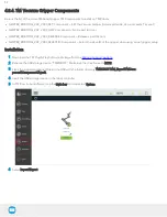
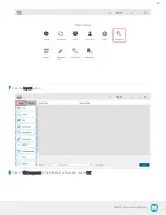
Страница 57: ...7 Click on the New Project icon in the upper left corner of the screen 57...
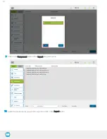
Страница 58: ...AirPick Instruction Manual 8 Enter a name for your program and click on the OK button 9 58...
Страница 76: ...Fig 6 5 Minimum and maximum arrangement possibilities of the air nodes position 76...
Страница 77: ...AirPick Instruction Manual 6 1 3 Air nodes Fig 6 6 Air nodes dimensions 77...
Страница 103: ...AirPick Instruction Manual 12 Appendix Fig 12 1 Pneumatic schema of the AirPick Vacuum Gripper...