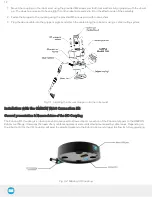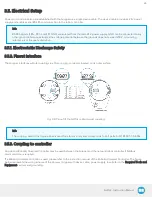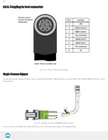
3.5.4. Coupling to tool connector
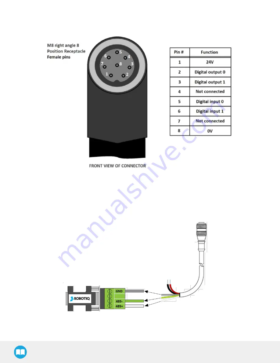
Fig. 3-11: Pinout of the I/O Coupling
Single Vacuum Gripper
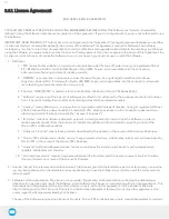
Connect the white, green and bare wires to the Robotiq RS485 to RS232 signal converter (ACC-ADT-RS232-RS485) as shown in the
figure below.
Fig. 3-12: Gripper cable to RS485/RS232 converter
Also connect the red (24V) and black (0V) wires in the controller according to the figure bellow.
29
Содержание AirPick
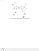
Страница 25: ...Fig 3 7 Mounting air nodes suction cups air bolts air nuts on the bracket 25...
Страница 27: ...Fig 3 9 Robotiq Vacuum Gripper with pigtail cable and device cable wiring scheme 27...
Страница 35: ...Fig 4 1 Vacuum Gripper control logic overview 35...
Страница 57: ...7 Click on the New Project icon in the upper left corner of the screen 57...
Страница 58: ...AirPick Instruction Manual 8 Enter a name for your program and click on the OK button 9 58...
Страница 76: ...Fig 6 5 Minimum and maximum arrangement possibilities of the air nodes position 76...
Страница 77: ...AirPick Instruction Manual 6 1 3 Air nodes Fig 6 6 Air nodes dimensions 77...
Страница 103: ...AirPick Instruction Manual 12 Appendix Fig 12 1 Pneumatic schema of the AirPick Vacuum Gripper...


