ROBERTS GORDON
®
CORAYVAC
®
M
ODULATING
H
EATING
C
ONTROL
C
ONTROLLER
I
NSTALLATION
M
ANUAL
52
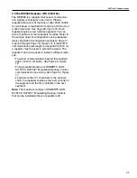
6.2.3 Reset to Factory Default Setting
To reset VFD to the factory default setting, press the
Up + Down +Stop buttons simultaneously for 5 sec-
onds. The display will read P-DEF. Press Stop button
to clear screen. Press and hold OK. Reprogram the
parameter according to the instructed recommended
settings.
6.3 Sequence of Operation CORAYVAC
®
Modulating Heating Control
(CORAYVAC
®
System (Modulating))
1. On a call for heat from zone sensor, controller will
verify that vacuum pump air pressure switch is open.
If switch is open, VFD 'Run' command will be issued
to start vacuum pump, vacuum pump LED on control
panel will be lit, and vacuum pump will start immedi-
ately at 100% speed. If controller verifies that vacuum
pump air pressure switch is closed during initial start,
a fault alarm will be activated, and the system will not
start. OPTION: If outside air blower is installed,
blower will start when VFD 'Run' command is issued.
2. After a short run period, vacuum pressure switch
will close, zone LED on control panel will be lit and a
signal is sent to start all burners in the zone to begin
ignition sequence.
3. Burner ignition module will provide a pre-purge of
approximately 45 seconds prior to ignition. After pre-
purge, gas valve will open, and flame is established.
If flame is detected by burner flame sensor, burner
gas valves remain open. If flame is not established,
burner ignition sequence will repeat. After three trials,
the burner module will lockout for one hour or until
manual reset.
Note:
Burners in zone may not all fire at exact same
time. Ignition of all burners in zone may vary 3 - 5
seconds.
4. Vacuum pump will run at 100% speed for 2 min-
utes from time that initial 'Run' command is issued.
5. Modulation period begins after 2-minute initial run
period. CORAYVAC
®
Modulating Heating Control
compares outdoor air temperature with zone tem-
perature setpoint and will modulate the CORAYVAC
®
system appropriately to meet zone temperature set-
point.
6. If zone temperature falls X °F (Default = 5 °F)
below desired setpoint, or if zone temperature is not
changed within 1 °F of setpoint within 30 minutes of
heat cycle, 100% heat request issued.
7. When the call for heat is satisfied, burners shut off,
zone LED light on control panel turns off.
8. The pump will continue operation at 100% speed
for a post-purge period of 2 minutes.
9. After the post-purge period, VFD will drop 'Run'
command and vacuum pump and vacuum pump
LED simultaneously turn off.
OPTION:
If outside air blower is installed, blower will
turn off after post purge period.
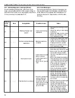
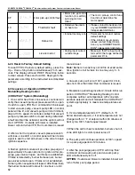
0F
SPl n-F
Motor pick-up control fault
• Motor pick-up control
function (for catching
spinning motors)
failed
• The motor pick-up control func-
tion did not determine the
motor speed.
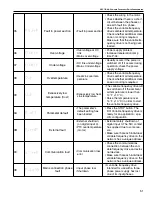
10
th-Frt
Thermistor fault
• Defective thermistor
on heat sink
• Please contact Roberts-Gordon
or your ROBERTS GORDON
®
independent distributor.
11
dAtA-F
Data error
• Internal memory error
• Parameter not stored: restore
default settings.
• If the problem occurs again,
please contact Roberts-Gor-
don or your ROBERTS GOR-
DON
®
independent distributor.
12
4-20FR
Live zero error
• Analog input current
outside range
• Make sure that the input current
falls within the range defined in
parameter P-16.
Содержание CORAYVAC
Страница 2: ......
Страница 4: ......
Страница 69: ...SECTION 8 PROGRAMMING AND TROUBLESHOOTING THE SYSTEM 65 THIS PAGE LEFT INTENTIONALLY BLANK ...
Страница 71: ...SECTION 9 TROUBLESHOOTING 67 FIGURE 26 Vacuum pump does not turn on ...
Страница 73: ...SECTION 9 TROUBLESHOOTING 69 FIGURE 28 VFD showing a fault sign FIGURE 29 VFD input power issue ...
Страница 75: ...SECTION 9 TROUBLESHOOTING 71 FIGURE 31 Burner troubleshooting in manual mode ...
Страница 77: ...SECTION 9 TROUBLESHOOTING 73 After 45 second prepurge burners do not light continued ...
Страница 79: ...SECTION 9 TROUBLESHOOTING 75 FIGURE 34 APS does not close within 60 seconds after VFD receives run command ...
Страница 81: ...SECTION 9 TROUBLESHOOTING 77 FIGURE 36 Air Pressure Switch alarm ...
Страница 83: ...SECTION 9 TROUBLESHOOTING 79 FIGURE 38 Repeater troubleshooting ...
Страница 85: ...SECTION 9 TROUBLESHOOTING 81 BACnet MS TP troubleshooting continued ...
Страница 109: ...SECTION 13 TOUCHSCREEN TREE 105 Touchscreen Tree Overview continued ...
Страница 111: ...SECTION 13 TOUCHSCREEN TREE 107 FIGURE 47 Maintenance Unit FIGURE 48 Alarms ...
Страница 113: ...SECTION 13 TOUCHSCREEN TREE 109 FIGURE 51 Configuration Zones FIGURE 52 Configuration Unit ...
Страница 115: ...SECTION 13 TOUCHSCREEN TREE 111 FIGURE 55 Touchscreen System FIGURE 56 Touchscreen Setup ...
Страница 118: ...ROBERTS GORDON CORAYVAC MODULATING HEATING CONTROL CONTROLLER INSTALLATION MANUAL 114 ...
Страница 119: ...SECTION 14 THE ROBERTS GORDON CORAYVAC COMPLETE MODULATING HEATING CONTROL LIMITED WARRANTY 115 ...

