SECTION 1: I
NTRODUCTION
1
SECTION 1: INTRODUCTION
1.1 Safety
Your Safety is Important to Us!
This symbol is used throughout
the manual to notify you of
possible fire, electrical or burn
hazards. Please pay special atten-
tion when reading and following
the warnings in these sections.
Installation, service and annual inspection of
controller must be done by an electrician qualified in
the installation and service of control systems for
heating equipment.
Installation, service and annual inspection of heater
must be done by a contractor qualified in the
installation and service of gas-fired heating
equipment.
Read this manual carefully before installation,
operation, or service of this equipment.
The appliance must be applied and operated under
the general concepts of reasonable use and installed
using best building practices.
This appliance is not intended for use by persons
(including children) with reduced physical, sensory or
mental capabilities, or lack of experience and knowl-
edge, unless they have been given supervision or
instruction concerning use of the appliance by a per-
son responsible for their safety.
Children should be supervised to ensure that they do
not play with the appliance.
For optimum heater performance and safe heating
conditions, inspect and maintain heater(s) before
every heating season and as necessary. Also, know
and maintain heater clearances to combustibles, see
heater Installation, Operation and Service Manual for
further details. If you require additional manuals, con-
tact your ROBERTS GORDON
®
independent distrib-
utor or Roberts-Gordon LLC at (716) 852-4400, (800)
828-7450 or at www.robertsgordon.com.
1.2 Safety Labels and Their Placement
Product safety signs or labels should be replaced by
the product user when they are no longer legible.
Please contact Roberts-Gordon LLC or your ROB-
ERTS GORDON
®
independent distributor to obtain
replacement signs or labels.
1.3 California Proposition 65
In accordance with California Proposition 65 require-
ments, a warning label must be placed in a highly
visible location on the outside of the equipment (i.e.,
near equipment’s serial plate). See label placement
drawings
for label location. Avoid placing label on areas with
extreme heat, cold, corrosive chemicals or other ele-
ments. To order additional labels, please contact
Roberts-Gordon LLC or your ROBERTS GORDON
®
independent distributor.
1.4 What is a ROBERTS GORDON
®
CORAYVAC
®
Modulating Heating Control?
The ROBERTS GORDON
®
CORAYVAC
®
Modulating
Heating Control is a micro-processor based control
package designed for modulating control of CORAY-
VAC
®
system and/or control of ROBERTS GOR-
DON
®
modulating and single stage unitary heaters
based on outdoor temperatures.
This controller is capable of giving control outputs to
two vacuum pumps and four heating zones. The con-
troller also features inputs which are used for indoor
and outdoor signal condition monitoring.
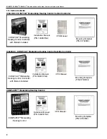
For the overall view of connected components for
ROBERTS GORDON
®
CORAYVAC
®
Modulating
Heating Control,
.
System status and settings are viewed and altered
from a touchscreen, personal computer or smart
device (PC and smart device not supplied).
1.5 What is a ROBERTS GORDON
®
COMPLETE™
Modulating Heating Control?
Similar to the CORAYVAC
®
Modulating Heating Con-
trol, The ROBERTS GORDON
®
COMPLETE™ Mod-
ulating Heating Control is a micro-processor based
control package designed for modulating control of
VANTAGE
®
Modulating (model: CTH3/HEM) unitary
heaters, on/off control of single-stage ROBERTS
GORDON
®
unitary heaters, or on/off control of
CORAYVAC
®
or VANTAGE
®
Multiburner systems.
This controller is capable of giving control outputs to
two vacuum pumps and four heating zones. The con-
troller also features inputs which are used for indoor
and outdoor signal condition monitoring.
System status and settings are viewed and altered
from a touchscreen, personal computer, or smart
device (PC and smart device not supplied).
Содержание CORAYVAC
Страница 2: ......
Страница 4: ......
Страница 69: ...SECTION 8 PROGRAMMING AND TROUBLESHOOTING THE SYSTEM 65 THIS PAGE LEFT INTENTIONALLY BLANK ...
Страница 71: ...SECTION 9 TROUBLESHOOTING 67 FIGURE 26 Vacuum pump does not turn on ...
Страница 73: ...SECTION 9 TROUBLESHOOTING 69 FIGURE 28 VFD showing a fault sign FIGURE 29 VFD input power issue ...
Страница 75: ...SECTION 9 TROUBLESHOOTING 71 FIGURE 31 Burner troubleshooting in manual mode ...
Страница 77: ...SECTION 9 TROUBLESHOOTING 73 After 45 second prepurge burners do not light continued ...
Страница 79: ...SECTION 9 TROUBLESHOOTING 75 FIGURE 34 APS does not close within 60 seconds after VFD receives run command ...
Страница 81: ...SECTION 9 TROUBLESHOOTING 77 FIGURE 36 Air Pressure Switch alarm ...
Страница 83: ...SECTION 9 TROUBLESHOOTING 79 FIGURE 38 Repeater troubleshooting ...
Страница 85: ...SECTION 9 TROUBLESHOOTING 81 BACnet MS TP troubleshooting continued ...
Страница 109: ...SECTION 13 TOUCHSCREEN TREE 105 Touchscreen Tree Overview continued ...
Страница 111: ...SECTION 13 TOUCHSCREEN TREE 107 FIGURE 47 Maintenance Unit FIGURE 48 Alarms ...
Страница 113: ...SECTION 13 TOUCHSCREEN TREE 109 FIGURE 51 Configuration Zones FIGURE 52 Configuration Unit ...
Страница 115: ...SECTION 13 TOUCHSCREEN TREE 111 FIGURE 55 Touchscreen System FIGURE 56 Touchscreen Setup ...
Страница 118: ...ROBERTS GORDON CORAYVAC MODULATING HEATING CONTROL CONTROLLER INSTALLATION MANUAL 114 ...
Страница 119: ...SECTION 14 THE ROBERTS GORDON CORAYVAC COMPLETE MODULATING HEATING CONTROL LIMITED WARRANTY 115 ...


