ROBERTS GORDON
®
CORAYVAC
®
M
ODULATING
H
EATING
C
ONTROL
C
ONTROLLER
I
NSTALLATION
M
ANUAL
50
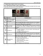
6.2.1 Acknowledge error message (Reset)
To acknowledge and reset the current error mes-
sage, you can either switch off the supply voltage or
press the STOP button. Error messages (a maximum
of four) are stored in parameter P-13.
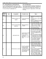
6.2.2 Error Messages
The following table shows the Error messages list,
the possible causes and indicates corrective mea-
sures. Refer to the supplied VFD installation and
operation manual for more details or VFD trouble-
shooting.
Failure
Code
[hex]
View
Designation
Possible Cause
Notes
01
01-b
Braking chopper over
current
• Overcurrent braking
resistance
• Overcurrent in braking resistor
circuit.
• Check the wiring to the braking
resistance.
• Check the brake resistor value.
Make sure to adhere to mini-
mum resistance values.
02
0L-br
Thermal overload braking
resistance
• Braking resistance
overload
• Increase the deceleration time,
reduce the load's moment of
inertia, or connect additional
braking resistors in parallel.
• Make sure to adhere to mini-
mum resistance values.
03
0-I
Overcurrent motor
• Overcurrent at output
• Motor overload
• Overtemperature at
heat sink
• Short circuit / ground
fault
• Motor with constant speed:
Determine the overload or fault.
• Motor starts: The load stalled or
has seized. Check whether
there is a star/delta motor wir-
ing error.
• Motor accelerates/decelerates:
The excessively short accelera-
tion/deceleration time is requir-
ing too much power. If P-03 or
P-04 cannot be increased, a
more powerful variable fre-
quency drive is required.
• Cable fault between variable
frequency drive and motor.
04
It-trF
Thermal motor overload
• The DC1 variable fre-
quency drive was
switched off after
more than 100% of
the value set in P-08
was delivered for a
period of time
• Check whether the decimal
places are flashing (variable
frequency drive overloaded)
and either raise the accelera-
tion ramp (P-03) or reduce the
motor load.
• Make sure that the cable length
matches the variable fre-
quency drive specifications.
• Check the load mechanically in
order to make sure that it is
free, that nothing is getting
jammed or locked, and there
are no other mechanical faults.
Содержание CORAYVAC
Страница 2: ......
Страница 4: ......
Страница 69: ...SECTION 8 PROGRAMMING AND TROUBLESHOOTING THE SYSTEM 65 THIS PAGE LEFT INTENTIONALLY BLANK ...
Страница 71: ...SECTION 9 TROUBLESHOOTING 67 FIGURE 26 Vacuum pump does not turn on ...
Страница 73: ...SECTION 9 TROUBLESHOOTING 69 FIGURE 28 VFD showing a fault sign FIGURE 29 VFD input power issue ...
Страница 75: ...SECTION 9 TROUBLESHOOTING 71 FIGURE 31 Burner troubleshooting in manual mode ...
Страница 77: ...SECTION 9 TROUBLESHOOTING 73 After 45 second prepurge burners do not light continued ...
Страница 79: ...SECTION 9 TROUBLESHOOTING 75 FIGURE 34 APS does not close within 60 seconds after VFD receives run command ...
Страница 81: ...SECTION 9 TROUBLESHOOTING 77 FIGURE 36 Air Pressure Switch alarm ...
Страница 83: ...SECTION 9 TROUBLESHOOTING 79 FIGURE 38 Repeater troubleshooting ...
Страница 85: ...SECTION 9 TROUBLESHOOTING 81 BACnet MS TP troubleshooting continued ...
Страница 109: ...SECTION 13 TOUCHSCREEN TREE 105 Touchscreen Tree Overview continued ...
Страница 111: ...SECTION 13 TOUCHSCREEN TREE 107 FIGURE 47 Maintenance Unit FIGURE 48 Alarms ...
Страница 113: ...SECTION 13 TOUCHSCREEN TREE 109 FIGURE 51 Configuration Zones FIGURE 52 Configuration Unit ...
Страница 115: ...SECTION 13 TOUCHSCREEN TREE 111 FIGURE 55 Touchscreen System FIGURE 56 Touchscreen Setup ...
Страница 118: ...ROBERTS GORDON CORAYVAC MODULATING HEATING CONTROL CONTROLLER INSTALLATION MANUAL 114 ...
Страница 119: ...SECTION 14 THE ROBERTS GORDON CORAYVAC COMPLETE MODULATING HEATING CONTROL LIMITED WARRANTY 115 ...

