SECTION 3: I
NSTALLATION
13
SECTION 3: INSTALLATION
Installation of CORAYVAC
®
Modulating Heating Con-
trol and associated external electrical wiring must be
done by an electrician qualified in the installation of
control systems for heating equipment.
3.1 Preparation
Before installing controller, observe the following:
3.1.1
Ensure that you have a copy of the site layout
for the project that clearly identifies the separate
zones and wiring distances between all components.
3.1.2
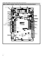
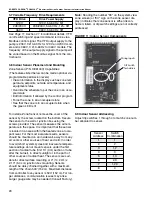
Familiarize yourself with the Controller and Vari-
able Frequency Drive component names and loca-
tions.
Note:
The VFD is located inside of the CORAYVAC
®
Modulating Heating Control panel. Be sure to plan
accordingly.
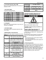
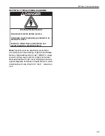
DANGER
Electrical Shock Hazard
Disconnect electric before service.
Controller must be properly grounded to an
electrical source.
Failure to follow these instructions can
result in death or electrical shock.
Содержание CORAYVAC
Страница 2: ......
Страница 4: ......
Страница 69: ...SECTION 8 PROGRAMMING AND TROUBLESHOOTING THE SYSTEM 65 THIS PAGE LEFT INTENTIONALLY BLANK ...
Страница 71: ...SECTION 9 TROUBLESHOOTING 67 FIGURE 26 Vacuum pump does not turn on ...
Страница 73: ...SECTION 9 TROUBLESHOOTING 69 FIGURE 28 VFD showing a fault sign FIGURE 29 VFD input power issue ...
Страница 75: ...SECTION 9 TROUBLESHOOTING 71 FIGURE 31 Burner troubleshooting in manual mode ...
Страница 77: ...SECTION 9 TROUBLESHOOTING 73 After 45 second prepurge burners do not light continued ...
Страница 79: ...SECTION 9 TROUBLESHOOTING 75 FIGURE 34 APS does not close within 60 seconds after VFD receives run command ...
Страница 81: ...SECTION 9 TROUBLESHOOTING 77 FIGURE 36 Air Pressure Switch alarm ...
Страница 83: ...SECTION 9 TROUBLESHOOTING 79 FIGURE 38 Repeater troubleshooting ...
Страница 85: ...SECTION 9 TROUBLESHOOTING 81 BACnet MS TP troubleshooting continued ...
Страница 109: ...SECTION 13 TOUCHSCREEN TREE 105 Touchscreen Tree Overview continued ...
Страница 111: ...SECTION 13 TOUCHSCREEN TREE 107 FIGURE 47 Maintenance Unit FIGURE 48 Alarms ...
Страница 113: ...SECTION 13 TOUCHSCREEN TREE 109 FIGURE 51 Configuration Zones FIGURE 52 Configuration Unit ...
Страница 115: ...SECTION 13 TOUCHSCREEN TREE 111 FIGURE 55 Touchscreen System FIGURE 56 Touchscreen Setup ...
Страница 118: ...ROBERTS GORDON CORAYVAC MODULATING HEATING CONTROL CONTROLLER INSTALLATION MANUAL 114 ...
Страница 119: ...SECTION 14 THE ROBERTS GORDON CORAYVAC COMPLETE MODULATING HEATING CONTROL LIMITED WARRANTY 115 ...


