SECTION 3: I
NSTALLATION
15
3.2 Positioning CORAYVAC
®
Modulating Heating
Control
3.2.1
For serviceability, it is convenient to mount the
controller at occupant level in the vicinity of the
pump. For proper frequency between the VFD and
pump, the wire length between controller and vac-
uum pump should not be more than 100' (30 m). A
Load Reactor (P/N 100610XX) will be required for
distances greater than 100' (30 m). Maximum dis-
tance with Load Reactor is 400' (120 m). Load reac-
tor should be mounted as close to VFD as possible.
Consult factory if distance required is greater.
Do not mount controller outdoors.
Controller must
not be installed where subjected to adverse condi-
tions such as: combustible, oily, or hazardous vapors
or dust; excessive moisture or dirt; vibration. To avoid
damage from possible condensation leaks, do not
mount controller directly beneath pump. Avoid install-
ing the controller in mezzanines, direct sunlight, or
near external heat sources because these locations
usually have unpredictable temperature rises.
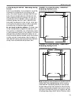
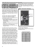
FIGURE 7: Controller Mounting - CORAYVAC
®
Modulating Heating Control
(Dimensions shown in inches)
FIGURE 8: Controller Mounting - COMPLETE™
Modulating Heating Control
(Dimensions shown in inches)
Note:
A paper mounting template is included with the
CORAYVAC
®
Modulating Heating Control and the
COMPLETE™ Modulating Heating Control panels.
Appropriately position the template on the mounting
surface, ensuring the template is level prior to mark-
ing each mounting hole shown on template. Pre-drill
mounting holes using a 9/32" drill bit. Position control
0.33
R0.16
R0.16
19.00
1.5 TYP.
1.5 TYP
1.5 TYP.
19.00
0.51
R0.27
R0.16
21.36
0.51
1.50
0.33
R0.16
R0.16
1.5 TYP
1.5 TYP.
0.51
R0.27
R0.16
0.51
1.50
17.88
11.00
11.00
17.88
R0.16
R0.27
Содержание CORAYVAC
Страница 2: ......
Страница 4: ......
Страница 69: ...SECTION 8 PROGRAMMING AND TROUBLESHOOTING THE SYSTEM 65 THIS PAGE LEFT INTENTIONALLY BLANK ...
Страница 71: ...SECTION 9 TROUBLESHOOTING 67 FIGURE 26 Vacuum pump does not turn on ...
Страница 73: ...SECTION 9 TROUBLESHOOTING 69 FIGURE 28 VFD showing a fault sign FIGURE 29 VFD input power issue ...
Страница 75: ...SECTION 9 TROUBLESHOOTING 71 FIGURE 31 Burner troubleshooting in manual mode ...
Страница 77: ...SECTION 9 TROUBLESHOOTING 73 After 45 second prepurge burners do not light continued ...
Страница 79: ...SECTION 9 TROUBLESHOOTING 75 FIGURE 34 APS does not close within 60 seconds after VFD receives run command ...
Страница 81: ...SECTION 9 TROUBLESHOOTING 77 FIGURE 36 Air Pressure Switch alarm ...
Страница 83: ...SECTION 9 TROUBLESHOOTING 79 FIGURE 38 Repeater troubleshooting ...
Страница 85: ...SECTION 9 TROUBLESHOOTING 81 BACnet MS TP troubleshooting continued ...
Страница 109: ...SECTION 13 TOUCHSCREEN TREE 105 Touchscreen Tree Overview continued ...
Страница 111: ...SECTION 13 TOUCHSCREEN TREE 107 FIGURE 47 Maintenance Unit FIGURE 48 Alarms ...
Страница 113: ...SECTION 13 TOUCHSCREEN TREE 109 FIGURE 51 Configuration Zones FIGURE 52 Configuration Unit ...
Страница 115: ...SECTION 13 TOUCHSCREEN TREE 111 FIGURE 55 Touchscreen System FIGURE 56 Touchscreen Setup ...
Страница 118: ...ROBERTS GORDON CORAYVAC MODULATING HEATING CONTROL CONTROLLER INSTALLATION MANUAL 114 ...
Страница 119: ...SECTION 14 THE ROBERTS GORDON CORAYVAC COMPLETE MODULATING HEATING CONTROL LIMITED WARRANTY 115 ...


