3. INSTALLATION
3.1. INSTALLING THE MACHINE
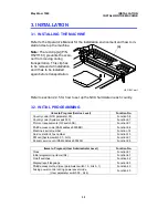
Refer to the Operator’s Manual for the installation environment and how to in-
stall and set up the machine.
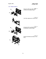
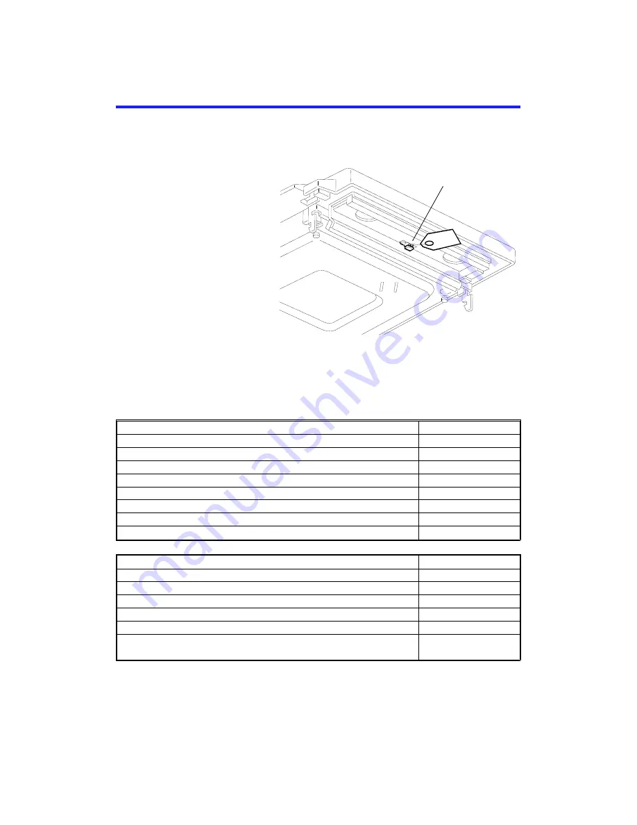
Note: The red clip [A] (P/N
H5211161) prevents the scan-
ner from moving during
transportation. This clip has
to be removed at installation,
and it has to be installed
again before transportation.
Refer to section 2.4.5 for how to set up the NCU hardware in each country.
3.2. INITIAL PROGRAMMING
Items to Program (Service Level)
Function No.
Country code (NCU parameter 00)
Function 08
Country code (System switch 0F)
Function 01
Protocol requirements (G3 switch 0B)
Function 01
PABX access code (RAM address 8000BB)
Function 06
Machine’s serial number
Function 14
Service station’s fax number
Function 13
PM call (System switch 01 - bit 0)
Function 01
Periodic service call (RAM address 800256)
Function 06
Items to Program (User Administrator Level)
Function No.
Clock
Function 91
Initial programming items (IDs)
Function 61
On/off switches
Function 62
Display/report language
Function 93
PABX access method (User parameter switch 13 - bits 0, 1)
Function 63
Fusing power control during power saver mode
(User parameter switch 05 - bit 6)
Function 63
[A]
H521I501.wmf
May 22nd, 1995
INSTALLATION
INSTALLING THE MACHINE
3-1

