4-5
ROTALIGN 01.2000
Q
UICK
C
HECK
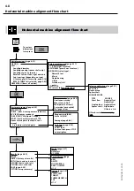
Compare these results with the machine specifications. If alignment
is required, press the COUPLING softkey
—
a warning appears inform-
ing that the last measurement made will be overwritten; press OK
and proceed from page 4-16.
Adjust the two dots into the central ring on the screen target (Check
that the laser and receiver are parallel and appear aligned by eye).
When centered, press S
TART
(if requested) and rotate the shafts a full
turn, or as far as possible
—
at least 75°. The receiver makes a series of
measurements; at least 5 are required. Once these conditions have
been met, the results screen appears...
4. Results
LEFT AND RIGHT
FOOT POSITIONS
LEFT MACHINE
RIGHT MACHINE
OFFSET
ANGLE
VERTICAL
VIEW FROM
SIDE
HORIZONTAL
VIEW FROM
ABOVE
Switches to main
horizontal alignment
mode (page 4-6)
Note:
1 mrad = 1 micron / mm
= 1 mil / inch
Remember:
Remove all components from
the shaft before restarting the
machine!
Align laser,
press START
and rotate
CENTERED!
Adjust laser, press START to measure
3. Adjust beam and measure
The measurement screen appears. Switch on laser and center the
beam onto the receiver dustcap with the two thumbwheels on the
laser. Remove the dustcap and view the target on the screen (page
4-23):
Содержание ROTALIGN ALI 3.500
Страница 13: ...1 10 ROTALIGN 01 2000 This page intentionally left blank ...
Страница 103: ...4 66 ROTALIGN 01 2000 This page intentionally left blank ...
Страница 121: ...5 18 ROTALIGN 01 2000 This page intentionally left blank ...
Страница 143: ...6 22 ROTALIGN 01 2000 This page has intentionally been left blank ...
Страница 158: ...6 37 ROTALIGN 01 2000 This page intentionally left blank ...


