MAINTENANCE
2.13
THROTTLE OPERATION
Check for smooth throttle opening and closing in all han-
dlebar positions.
Throttle lever operation should be
smooth and lever must return freely without binding.
1.
Place the gear selector in neutral.
2.
Set parking brake.
3.
Start the engine and let it idle.
4.
Turn handlebars from full right to full left. If idle speed
increases at any point in the turning range, inspect
throttle cable routing and condition.
5.
Replace the throttle cable if worn, kinked, or damaged.
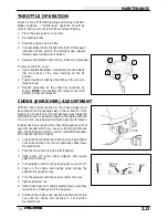
To remove the ETC cover:
1.
Use a medium flat blade screwdriver and insert blade
into the pocket of the cover starting on the #1
position.
2.
Twist screwdriver slightly while lifting on the cover to
release snap.
3.
Repeat procedure at the other five locations as
shown. NOTE: Do not attempt to remove cover until
all latch points are released.
CHOKE (ENRICHER) ADJUSTMENT
With the choke control pushed in, the choke plunger must
be seated on the fuel passage way in the carburetor. If the
plunger is not seated on the fuel passage way inside the
carburetor (not enough cable freeplay), the engine will flood
or run too rich, causing plug fouling and poor performance.
If cable slack is excessive, the choke fuel passage will not
open far enough, which may cause cold starting difficulty.
Also, the half-choke position used for intermittent applica-
tions will not function properly.
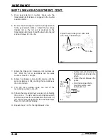
1.
Locate the boot behind the choke knob and pull it back.
Loosen the friction nut 1 turn or until choke slides freely.
Re-install boot.
2.
Push the choke knob in to the full off position.
3.
Slide boots off in-line cable adjuster and loosen
adjustment locknut.
4.
Turn adjuster until the choke knob pulls out over 1/4
″
.
5.
Push on the choke knob lightly while turning the
adjuster the opposite way.
6.
Turn the adjuster until the knob contacts the boot.
7.
Tighten adjuster nut.
8.
Slide boots back over cable adjuster sleeve until they
touch at the middle point of the adjuster.
9.
Pull back the choke knob boot and tighten the friction
nut until the choke will maintain a set position.
Re-install boot.
1
2
3
4
5
6
5
6
Boot
Adjuster
Sleeve
Lock-
nut
Boot
Содержание Sportsman 400
Страница 5: ...SPORTSMAN 400 A01CH42AB SPORTSMAN 400 A01CH42AA GENERAL INFORMATION 1 3 MODEL COLOR IDENTIFICATION ...
Страница 6: ...SPORTSMAN 400 A01CH42AC GENERAL INFORMATION 1 4 MODEL COLOR IDENTIFICATION ...
Страница 21: ...Newton Meter to Pound Foot and Pound Inch GENERAL INFORMATION 1 19 TORQUE CONVERSIONS ...
Страница 22: ...Newton Meter to Pound Foot and Pound Inch GENERAL INFORMATION 1 20 TORQUE CONVERSIONS ...
Страница 94: ...ENGINE 3 25 CYLINDER HEAD EXPLODED VIEW 1 Remove the two 6mm flange bolts A from cylinder head A ...
Страница 152: ...Forward FUEL SYSTEM CARBURETION 4 2 FUEL TANK ASSEMBLY ...
Страница 325: ...BRAKES 9 22 FRONT BRAKE CALIPER EXPLODED VIEW Pads Caliper Mount Piston Pin Boot Square O Rings Adjuster Screw ...
Страница 366: ...ELECTRONIC SPEEDOMETER WIRING DIAGRAM ELECTRICAL 10 32 ...
Страница 372: ...ELECTRICAL 10 38 NOTES ...
Страница 379: ...ELECTRICAL 10 39 WIRING DIAGRAM 2001 SPORTSMAN 400 ...
Страница 380: ...ELECTRICAL 10 40 WIRING DIAGRAM 2001 SPORTSMAN 500 EARLY ...
Страница 381: ...ELECTRICAL 10 41 WIRING DIAGRAM 2001 SPORTSMAN 500 LATE ...

