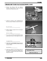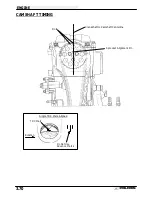
Guide in
recess
ENGINE
3.67
CYLINDER INSTALLATION, CONT.
7.
Apply a light film of oil to the threads and flange
surface of the cylinder mounting bolts.
8.
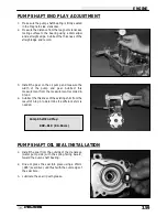
Install all four bolts finger tight. Rotate the engine and
position the piston at BDC.
NOTE: If cam chain is installed, hold it up while rotating
the engine to avoid damage to the chain, drive sprocket
teeth, or tensioner blade.
9.
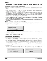
Tighten the cylinder bolts in three steps in a criss cross
pattern and torque to specifications.
10. Install the two 6mm bolts.
CYLINDER HEAD INSTALLATION
Clean the gasket surfaces on the cylinder head and cylin-
der. Remove all traces of old gasket material.
Refer to disassembly photos.
1.
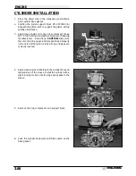
Install the cam chain tensioner guide. Be sure bottom
end of guide is located properly in crankcase.
2.
Install the two dowel pins and a new cylinder head
gasket.
3.
Place the cylinder head on the cylinder. Apply a film of
engine oil to the cylinder head bolt threads and
washers, and hand tighten the bolts.
The following procedure must be used to torque the
cylinder head properly:
Cylinder Bolt Torque:
10mm - 46 ft. lbs. (6.348 kg-m)
6mm - 6 ft. lbs. (.828 kg-m)
Torque all bolts evenly in a criss cross
pattern
*Torque bolts to 22 ft. lbs. (3.04 kg-m)
*Torque bolts to 51 ft. lbs. (7.04 kg-m)
*Loosen bolts evenly 180
°
(1/2 turn)
*Loosen bolts again another 180
°
(1/2
turn)
*Torque bolts to 11 ft. lbs. (1.52 kg-m)
*From this point, tighten bolts evenly
90
°
(1/4 turn)
*Finally, tighten another 90
°
(1/4 turn)
*Install two 6mm bolts and torque to 6
ft. lbs. (.828 kg-m)
Содержание Sportsman 400
Страница 5: ...SPORTSMAN 400 A01CH42AB SPORTSMAN 400 A01CH42AA GENERAL INFORMATION 1 3 MODEL COLOR IDENTIFICATION ...
Страница 6: ...SPORTSMAN 400 A01CH42AC GENERAL INFORMATION 1 4 MODEL COLOR IDENTIFICATION ...
Страница 21: ...Newton Meter to Pound Foot and Pound Inch GENERAL INFORMATION 1 19 TORQUE CONVERSIONS ...
Страница 22: ...Newton Meter to Pound Foot and Pound Inch GENERAL INFORMATION 1 20 TORQUE CONVERSIONS ...
Страница 94: ...ENGINE 3 25 CYLINDER HEAD EXPLODED VIEW 1 Remove the two 6mm flange bolts A from cylinder head A ...
Страница 152: ...Forward FUEL SYSTEM CARBURETION 4 2 FUEL TANK ASSEMBLY ...
Страница 325: ...BRAKES 9 22 FRONT BRAKE CALIPER EXPLODED VIEW Pads Caliper Mount Piston Pin Boot Square O Rings Adjuster Screw ...
Страница 366: ...ELECTRONIC SPEEDOMETER WIRING DIAGRAM ELECTRICAL 10 32 ...
Страница 372: ...ELECTRICAL 10 38 NOTES ...
Страница 379: ...ELECTRICAL 10 39 WIRING DIAGRAM 2001 SPORTSMAN 400 ...
Страница 380: ...ELECTRICAL 10 40 WIRING DIAGRAM 2001 SPORTSMAN 500 EARLY ...
Страница 381: ...ELECTRICAL 10 41 WIRING DIAGRAM 2001 SPORTSMAN 500 LATE ...


