CLUTCH
6.14
DRIVE CLUTCH DISASSEMBLY
1.
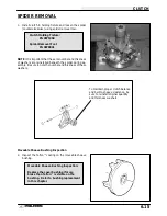
Using a permanent marker, mark the cover, spider,
and
moveable
and
stationary
sheaves
for
reference. The X’s may not have been in alignment
before disassembly.
2.
Remove cover bolts evenly in a cross pattern, and
remove cover plate.
3.
Inspect cover bushing (A). The outer cover bushing
is manufactured with a Teflon
™
coating. Bushing
wear is determined by the amount of Teflon
™
remaining on the bushing.
4.
Inspect area on shaft where bushing rides for wear,
galling, nicks, or scratches.
Replace clutch
assembly if worn or damaged.
5.
Remove and inspect spring. (See page 6.10)
Mark
“X”
Mark
A
Cover Bushing Inspection:
Replace the cover bushing if more
brass than Teflon
™
is visible on the
bushing. Refer to bushing replacement
in this chapter.
Inspect shaft
Содержание Sportsman 400
Страница 5: ...SPORTSMAN 400 A01CH42AB SPORTSMAN 400 A01CH42AA GENERAL INFORMATION 1 3 MODEL COLOR IDENTIFICATION ...
Страница 6: ...SPORTSMAN 400 A01CH42AC GENERAL INFORMATION 1 4 MODEL COLOR IDENTIFICATION ...
Страница 21: ...Newton Meter to Pound Foot and Pound Inch GENERAL INFORMATION 1 19 TORQUE CONVERSIONS ...
Страница 22: ...Newton Meter to Pound Foot and Pound Inch GENERAL INFORMATION 1 20 TORQUE CONVERSIONS ...
Страница 94: ...ENGINE 3 25 CYLINDER HEAD EXPLODED VIEW 1 Remove the two 6mm flange bolts A from cylinder head A ...
Страница 152: ...Forward FUEL SYSTEM CARBURETION 4 2 FUEL TANK ASSEMBLY ...
Страница 325: ...BRAKES 9 22 FRONT BRAKE CALIPER EXPLODED VIEW Pads Caliper Mount Piston Pin Boot Square O Rings Adjuster Screw ...
Страница 366: ...ELECTRONIC SPEEDOMETER WIRING DIAGRAM ELECTRICAL 10 32 ...
Страница 372: ...ELECTRICAL 10 38 NOTES ...
Страница 379: ...ELECTRICAL 10 39 WIRING DIAGRAM 2001 SPORTSMAN 400 ...
Страница 380: ...ELECTRICAL 10 40 WIRING DIAGRAM 2001 SPORTSMAN 500 EARLY ...
Страница 381: ...ELECTRICAL 10 41 WIRING DIAGRAM 2001 SPORTSMAN 500 LATE ...

