CLUTCH
6.3
PVT MAINTENANCE/INSPECTION
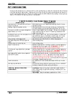
Under normal operation the PVT system will provide years of trouble free operation. Periodic inspection and main-
tenance is required to keep the system operating at peak performance. The following list of items should be in-
spected and maintained to ensure maximum performance and service life of PVT components. Refer to the trou-
bleshooting checklist at the end of this chapter for more information.
1.
Belt Tension, Drive to Driven Clutch Offset, Belt Width. See pages 6.18-6.21.
2.
Drive and Driven Clutch Buttons and Bushings, Drive Clutch Shift Weights and Pins, Drive Clutch
Spider Rollers and Roller Pins, Drive and Driven Clutch Springs. See pages 6.10-6.12.
3.
Sheave Faces. Clean and inspect for wear.
4.
PVT System Sealing. Refer to appropriate illustration below and on the following pages. The PVT system is
air cooled by fins on the drive clutch stationary sheave. The fins create a low pressure area in the crankcase
casting, drawing air into the system through an intake duct. The opening for this intake duct is located at a high
point on the vehicle (location varies by model). The intake duct draws fresh air through a vented cover. All
connecting air ducts (as well as the inner and outer covers) must be properly sealed to ensure clean air is
being used for cooling the PVT system and also to prevent water and other contaminants from entering the
PVT area. This is especially critical on units subjected to frequent water forging.
PVT DRYING
If water is ingested, shift transmission to neutral and rev engine slightly to expel the moisture and air-dry the
belt and clutches. Allow engine RPM to settle to idle speed, shift transmission to lowest available range and
test for belt slippage. Operate ATV in lowest available range for a short period of time until PVT system is
dry.
Содержание Sportsman 400
Страница 5: ...SPORTSMAN 400 A01CH42AB SPORTSMAN 400 A01CH42AA GENERAL INFORMATION 1 3 MODEL COLOR IDENTIFICATION ...
Страница 6: ...SPORTSMAN 400 A01CH42AC GENERAL INFORMATION 1 4 MODEL COLOR IDENTIFICATION ...
Страница 21: ...Newton Meter to Pound Foot and Pound Inch GENERAL INFORMATION 1 19 TORQUE CONVERSIONS ...
Страница 22: ...Newton Meter to Pound Foot and Pound Inch GENERAL INFORMATION 1 20 TORQUE CONVERSIONS ...
Страница 94: ...ENGINE 3 25 CYLINDER HEAD EXPLODED VIEW 1 Remove the two 6mm flange bolts A from cylinder head A ...
Страница 152: ...Forward FUEL SYSTEM CARBURETION 4 2 FUEL TANK ASSEMBLY ...
Страница 325: ...BRAKES 9 22 FRONT BRAKE CALIPER EXPLODED VIEW Pads Caliper Mount Piston Pin Boot Square O Rings Adjuster Screw ...
Страница 366: ...ELECTRONIC SPEEDOMETER WIRING DIAGRAM ELECTRICAL 10 32 ...
Страница 372: ...ELECTRICAL 10 38 NOTES ...
Страница 379: ...ELECTRICAL 10 39 WIRING DIAGRAM 2001 SPORTSMAN 400 ...
Страница 380: ...ELECTRICAL 10 40 WIRING DIAGRAM 2001 SPORTSMAN 500 EARLY ...
Страница 381: ...ELECTRICAL 10 41 WIRING DIAGRAM 2001 SPORTSMAN 500 LATE ...


