BODY / STEERING / SUSPENSION
5.11
BALL JOINT REPLACEMENT
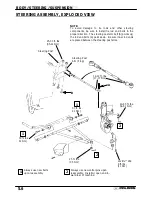
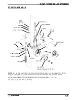
REFER TO ILLUSTRATION ON PAGE 5.9.
1.
Loosen front wheel nuts slightly.
2.
Elevate and safely support machine under
footrest/frame area.
CAUTION: Serious injury may result if machine tips
or falls. Be sure machine is secure before beginning
this service procedure.
3.
Remove wheel nuts and wheels.
4.
Remove cotter pin (A) from ball joint castlenut.
5.
Remove castle nut (B) and separate A-arm (C)
from ball joint stud.
6.
Remove screws (D) and ball joint retaining plate
plate (E).
7.
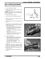
Using ball joint removal / installation tool kit (PN
2870871), remove ball joint (F) from strut housing.
Refer to photos at right.
S
Install puller guide (A) with extension cap (B).
S
Apply grease to extension cap and threads of
puller bolt to ease removal.
S
Thread bolt (D) with nut (C) onto ball joint stud
as shown.
S
Apply heat to ease removal.
S
Hold bolt (D) and turn nut (C) clockwise until
ball joint is removed from strut housing.
8.
To install new ball joint:
S
Remove extension cap and attach puller
guide using short bolts provided in the kit.
S
Insert new ball joint (E) into driver (F).
S
Slide ball joint/driver assembly into guide.
S
Apply heat to ease installation.
S
Drive new joint into strut housing until fully
seated.
9.
Apply Loctite
t
242 (blue) to threads of retaining
plate screws or install new screws with pre-applied
locking agent. Torque screws to 8 ft. lbs. (11 Nm).
10. Install A-arm on ball joint and torque castle nut to
25 ft. lbs. (35 Nm).
11. Reinstall cotter pin with open ends toward rear of
machine.
A
B
C
D
E
F
A
B
C
D
A
B
C
E
D
F
E
Содержание Sportsman 400
Страница 5: ...SPORTSMAN 400 A01CH42AB SPORTSMAN 400 A01CH42AA GENERAL INFORMATION 1 3 MODEL COLOR IDENTIFICATION ...
Страница 6: ...SPORTSMAN 400 A01CH42AC GENERAL INFORMATION 1 4 MODEL COLOR IDENTIFICATION ...
Страница 21: ...Newton Meter to Pound Foot and Pound Inch GENERAL INFORMATION 1 19 TORQUE CONVERSIONS ...
Страница 22: ...Newton Meter to Pound Foot and Pound Inch GENERAL INFORMATION 1 20 TORQUE CONVERSIONS ...
Страница 94: ...ENGINE 3 25 CYLINDER HEAD EXPLODED VIEW 1 Remove the two 6mm flange bolts A from cylinder head A ...
Страница 152: ...Forward FUEL SYSTEM CARBURETION 4 2 FUEL TANK ASSEMBLY ...
Страница 325: ...BRAKES 9 22 FRONT BRAKE CALIPER EXPLODED VIEW Pads Caliper Mount Piston Pin Boot Square O Rings Adjuster Screw ...
Страница 366: ...ELECTRONIC SPEEDOMETER WIRING DIAGRAM ELECTRICAL 10 32 ...
Страница 372: ...ELECTRICAL 10 38 NOTES ...
Страница 379: ...ELECTRICAL 10 39 WIRING DIAGRAM 2001 SPORTSMAN 400 ...
Страница 380: ...ELECTRICAL 10 40 WIRING DIAGRAM 2001 SPORTSMAN 500 EARLY ...
Страница 381: ...ELECTRICAL 10 41 WIRING DIAGRAM 2001 SPORTSMAN 500 LATE ...

