ELECTRICAL
10.2
HIGH BEAM HEADLIGHT ADJUSTMENT
The headlight beam can be adjusted to any position desired by turning the adjusting knob located on the bottom
right side of the headlight pod.
1. Place the vehicle on a level surface with the headlight
approximately 25’ (7.6 m) from a wall.
2. Measure the distance from the floor to the center of the
headlight and make a mark on the wall at the same height.
3. Start the engine and turn the headlight switch to high
beam.
4. Observe headlight aim. The most intense part of the
headlight beam should be aimed 2
″
(5.1 cm) below the
mark placed on the wall in step 2 NOTE: Rider weight
must be included on the seat. On machines with separate
low beam lights, the drop should be 8
″
(20.3 cm) in 25’
from the center of the low beam lamp.
5. Adjust beam to desired position .
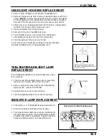
HIGH BEAM HEADLIGHT LAMP REPLACEMENT
CAUTION: Do not service
while headlight is hot. Serious
burns may result.
1. Remove three Phillips screws
at back of headlight pod.
2. Remove Phillips screws from
bottom of headlight pod at
each front corner. NOTE: To
aid
in
accessing
these
screws, it may be helpful to
turn handlebars to left or right
and use a short, stubby
screwdriver. Removal of the
front rack and cover will also
allow easier access.
3. Lift pod cover up.
4. Unplug headlamp from wiring
harness.
5. Remove rubber shield from
headlamp housing.
6. Push in and turn plastic re-
tainer counter clockwise and
remove.
7. Carefully remove headlamp
bulb from housing.
8. Reverse procedure to install
new headlamp bulb.
25’ (7.6 m)
Lamp Center Height
2
″
(5.1 cm)
Snap pins
into tabs
Position
knob in
slot and
secure
in lock-
ing tabs
Slip O-Ring
over pin
Adjustment
Knob Stop
Route
plug over
handlebar
Содержание Sportsman 400
Страница 5: ...SPORTSMAN 400 A01CH42AB SPORTSMAN 400 A01CH42AA GENERAL INFORMATION 1 3 MODEL COLOR IDENTIFICATION ...
Страница 6: ...SPORTSMAN 400 A01CH42AC GENERAL INFORMATION 1 4 MODEL COLOR IDENTIFICATION ...
Страница 21: ...Newton Meter to Pound Foot and Pound Inch GENERAL INFORMATION 1 19 TORQUE CONVERSIONS ...
Страница 22: ...Newton Meter to Pound Foot and Pound Inch GENERAL INFORMATION 1 20 TORQUE CONVERSIONS ...
Страница 94: ...ENGINE 3 25 CYLINDER HEAD EXPLODED VIEW 1 Remove the two 6mm flange bolts A from cylinder head A ...
Страница 152: ...Forward FUEL SYSTEM CARBURETION 4 2 FUEL TANK ASSEMBLY ...
Страница 325: ...BRAKES 9 22 FRONT BRAKE CALIPER EXPLODED VIEW Pads Caliper Mount Piston Pin Boot Square O Rings Adjuster Screw ...
Страница 366: ...ELECTRONIC SPEEDOMETER WIRING DIAGRAM ELECTRICAL 10 32 ...
Страница 372: ...ELECTRICAL 10 38 NOTES ...
Страница 379: ...ELECTRICAL 10 39 WIRING DIAGRAM 2001 SPORTSMAN 400 ...
Страница 380: ...ELECTRICAL 10 40 WIRING DIAGRAM 2001 SPORTSMAN 500 EARLY ...
Страница 381: ...ELECTRICAL 10 41 WIRING DIAGRAM 2001 SPORTSMAN 500 LATE ...

