A
Overview of Operation
The Polaris Electronic ATV speedometer is powered
by battery voltage (12 VDC) and requires engine
RPM, transmission gear, and wheel speed sensor
input signals for proper operation. Wiring to the
speedometer head consists of a three-pin connector
from the wheel speed sensor and a six-pin connector
from the main ATV wiring harness.
A non-serviceable internal memory battery main-
tains odometer and hour meter data when the ma-
chine is not running.
The illumination lamp inside the gauge is non-ser-
viceable and is designed to last for the life of the unit.
In addition to the ground speed in Miles Per Hour
(MPH) or Kilometers Per Hour (KPH), odometer, and
trip odometer, the electronic speedometer provides
the following functions:
S
Records Engine Run Time in Hours
S
Reverse Speed Limit
S
Prevents AWD engagement: When engine RPM
is too high
Vehicle Speed and Odometer
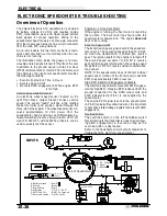
An electronic wheel speed sensor located on the
right front brake caliper bracket senses vehicle
speed. The sensor “reads” notches in the rotating
brake rotor (disc) and sends a signal through the
three-pin harness pin B. The wheel speed sensor re-
ceives approximately 10 VDC power from the
speedometer head and does not differentiate be-
tween forward and reverse wheel rotation. LED Test
Light PN 2871745, with 2460761 probe kit, can be
used to quickly test the sensor.
Engine Run Time Hour Meter
If the engine is running, the hour meter is recording
the run time. The hour meter logs hours when the
speedometer is powered up. The engine does not
have to be running.
Reverse Speed Limit
The transmission gear signal is sent to the speedom-
eter on pin F. The operating speed of the ATV is limit-
ed when the transmission is shifted into reverse
gear. The ignition spark to the engine is turned off if
the ground speed exceeds 7 to 9 MPH in reverse
gear. Ignition spark returns when the vehicle speed
drops below 7 MPH in reverse without override but-
ton pushed.
NOTE: If the speedometer does not detect a wheel
speed sensor (motion of the front wheel) it will limit
RPM to approximately 3600 in reverse.
High RPM AWD Hub Engagement Disable
The electronic speedometer prevents AWD engage-
ment at high RPM. If engine RPM is above 3000, the
ground connection for the AWD wheel coils and
AWD indicator lamp (Pin E) is not supplied by the
speedometer.
The engine RPM signal is sent to the speedometer
on Pin D (typically the yellow/red wire). It is important
to note that a failed voltage regulator can prevent AWD
engagement.
Override Button
The override button (on the left handlebar switch
block) interrupts the transmission gear signal allow-
ing AWD engagement in reverse as long as the
override button is depressed.
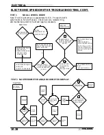
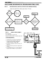
Refer to the flowcharts and schematic diagrams to
troubleshoot the electronic speedometer.
INPUTS
Back of Speedometer
E
A
B
C
D
F
B
C
Reverse(top trans sw.)
D.C.
(trans sw.)
A: Battery Voltage
- Red/W
B: Ground
- Brown
C: Engine Stop
- Black
D: Alternator
- Y/R, A.C., RPM
E: AWD Hub Coil
- Brn/W, Coil ground
F: Reverse Override
- Gry/Or, Limits
A: D.C. Power
B: Signal
C: Ground
Engine Off Switch
ELECTRICAL
10.26
ELECTRONIC SPEEDOMETER TROUBLESHOOTING
Содержание Sportsman 400
Страница 5: ...SPORTSMAN 400 A01CH42AB SPORTSMAN 400 A01CH42AA GENERAL INFORMATION 1 3 MODEL COLOR IDENTIFICATION ...
Страница 6: ...SPORTSMAN 400 A01CH42AC GENERAL INFORMATION 1 4 MODEL COLOR IDENTIFICATION ...
Страница 21: ...Newton Meter to Pound Foot and Pound Inch GENERAL INFORMATION 1 19 TORQUE CONVERSIONS ...
Страница 22: ...Newton Meter to Pound Foot and Pound Inch GENERAL INFORMATION 1 20 TORQUE CONVERSIONS ...
Страница 94: ...ENGINE 3 25 CYLINDER HEAD EXPLODED VIEW 1 Remove the two 6mm flange bolts A from cylinder head A ...
Страница 152: ...Forward FUEL SYSTEM CARBURETION 4 2 FUEL TANK ASSEMBLY ...
Страница 325: ...BRAKES 9 22 FRONT BRAKE CALIPER EXPLODED VIEW Pads Caliper Mount Piston Pin Boot Square O Rings Adjuster Screw ...
Страница 366: ...ELECTRONIC SPEEDOMETER WIRING DIAGRAM ELECTRICAL 10 32 ...
Страница 372: ...ELECTRICAL 10 38 NOTES ...
Страница 379: ...ELECTRICAL 10 39 WIRING DIAGRAM 2001 SPORTSMAN 400 ...
Страница 380: ...ELECTRICAL 10 40 WIRING DIAGRAM 2001 SPORTSMAN 500 EARLY ...
Страница 381: ...ELECTRICAL 10 41 WIRING DIAGRAM 2001 SPORTSMAN 500 LATE ...


