FINAL DRIVE
7.19
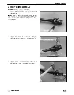
U-JOINT DISASSEMBLY
CAUTION: Always wear eye protection.
1.
Remove internal or external snap ring from all
bearing caps.
NOTE:If yoke or bearing is removed, cross bearing
must be replaced. Note orientation of grease fitting and
mark inner and outer yoke for correct re-positioning dur-
ing installation.
2.
Support inner yoke as shown and drive outer yoke
down (bearing cap out) with a soft face hammer.
3.
Support U-joint in vise as shown and drive inner
yoke down to remove remaining bearing caps.
Содержание Sportsman 400
Страница 5: ...SPORTSMAN 400 A01CH42AB SPORTSMAN 400 A01CH42AA GENERAL INFORMATION 1 3 MODEL COLOR IDENTIFICATION ...
Страница 6: ...SPORTSMAN 400 A01CH42AC GENERAL INFORMATION 1 4 MODEL COLOR IDENTIFICATION ...
Страница 21: ...Newton Meter to Pound Foot and Pound Inch GENERAL INFORMATION 1 19 TORQUE CONVERSIONS ...
Страница 22: ...Newton Meter to Pound Foot and Pound Inch GENERAL INFORMATION 1 20 TORQUE CONVERSIONS ...
Страница 94: ...ENGINE 3 25 CYLINDER HEAD EXPLODED VIEW 1 Remove the two 6mm flange bolts A from cylinder head A ...
Страница 152: ...Forward FUEL SYSTEM CARBURETION 4 2 FUEL TANK ASSEMBLY ...
Страница 325: ...BRAKES 9 22 FRONT BRAKE CALIPER EXPLODED VIEW Pads Caliper Mount Piston Pin Boot Square O Rings Adjuster Screw ...
Страница 366: ...ELECTRONIC SPEEDOMETER WIRING DIAGRAM ELECTRICAL 10 32 ...
Страница 372: ...ELECTRICAL 10 38 NOTES ...
Страница 379: ...ELECTRICAL 10 39 WIRING DIAGRAM 2001 SPORTSMAN 400 ...
Страница 380: ...ELECTRICAL 10 40 WIRING DIAGRAM 2001 SPORTSMAN 500 EARLY ...
Страница 381: ...ELECTRICAL 10 41 WIRING DIAGRAM 2001 SPORTSMAN 500 LATE ...


