background image

FASTCAM-ultima APX-i2 Hardware Manual 


-56- 

4.5. Selecting Trigger Mode 

 
The APX-i2 has several different modes of triggering to meet the particular needs of 
capturing varied, instantaneous events. 
This section discusses how each of the trigger modes works. 
 
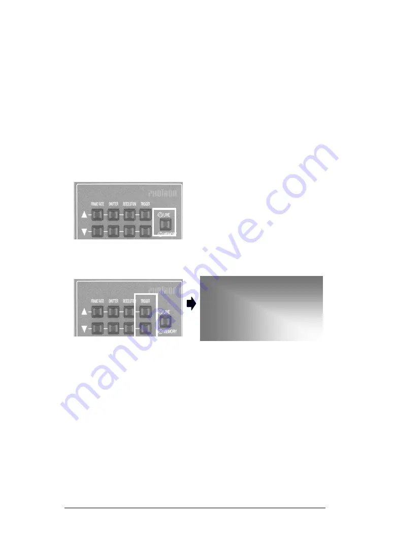
First, the procedure to select a trigger mode is shown, and then how each trigger mode 
works is discussed. 
 

1. Make sure that the camera is in the LIVE mode. 


2. Press the TRIGGER 

 or 

  button on the keypad to select a trigger mode. 


024X1024 1/3000s


ID01/01 LIVE 
START 
4096FR/2.048s


3. The selected trigger mode is displayed on the screen immediately. Make sure that 

the trigger mode indication changes as you press the 

 or 

 button.  


Содержание FASTCAM ultima APX-i2

Страница 1: ...FASTCAM ultima APX i2 Hardware Manual Rev 1 04 PHOTRON LIMITED SEP 2007...

Страница 2: ...FASTCAM ultima APX i2 Hardware Manual...

Страница 3: ...r IN Cable 22 2 3 System Connection 23 2 3 1 Connecting Camera Head 23 2 3 2 Connecting Remote Control Keypad 24 2 3 3 Connecting Video Monitor 25 2 3 4 Power Connection 26 2 4 Switching Power on 27 2...

Страница 4: ...tioning Memory 78 4 6 1 Prepare for Memory Partitioning Set Number of Sections 78 4 6 2 Recording into Divided Sections 79 4 6 3 Playback of Recorded Sections 79 4 6 4 PARTITION MODE 79 4 7 Look Up Ta...

Страница 5: ...113 5 10 Playback Event Markers 114 Chapter 6 Connecting APX i2 to a PC 115 6 1 Connecting APX i2 to a PC 116 6 1 1 APX i2 with IEEE1394 Interface 117 6 1 2 APX i2 with Ether Interface 117 6 1 3 Conne...

Страница 6: ...FASTCAM ultima APX i2 Hardware Manual 4 Memo...

Страница 7: ...FASTCAM ultima APX i2 Hardware Manual 5 Chapter 1 Introduction 1 1 Preface 1 2 Warranty 1 3 How to Use This Manual 1 4 Precautions...

Страница 8: ...ch easier means for analyzing captured events immediately which has been very difficult with conventional systems You will find this new recording technology most useful to capture the image of high s...

Страница 9: ...the APX i2 being subjected to accidental damage misuse or abuse If the APX i2 has been repaired or tampered with by persons other than PHOTRON personnel customer personnel trained by PHOTRON or withou...

Страница 10: ...rs If it is neglected and the equipment is used in the wrong manner a serious hazardous sequence involving human injury or death may result It must not be disregarded Chapters This manual is divided i...

Страница 11: ...f Part 15 of the FCC Rules and VDE 0871 Class B which are designed to provide reasonable protection against such interference when operated in a commercial environment Operation of this equipment in a...

Страница 12: ...lens and lens cap in place when not in use Operating the image intensifier while it is exposed to bright light e g ambient room illumination will cause serious damage to the intensifier s photocathod...

Страница 13: ...FASTCAM ultima APX i2 Hardware Manual 11 Memo...

Страница 14: ...ASTCAM ultima APX i2 Hardware Manual 12 Chapter 2 Set Up 2 1 To Start 2 2 Names of Components 2 3 System Connection 2 4 Switching power on 2 5 Basics of Remote Control Keypad Operation 2 5 System Setu...

Страница 15: ...12 MCDL IRIG Compound Cable 1 ea 13 Ferrite Core for Cable 1 ea 14 CD ROM for Driver Application Setup 1 ea 15 FASTCAM ultima APX i2 Hardware Manual 1 ea 16 FASTCAM Control Software Operation Manual...

Страница 16: ...n the video monitor an IEEE1394 digital interface to control the camera from a PC and download recorded image data input and output connectors for external sync and trigger signals and a port to accep...

Страница 17: ...s application The camera head has tripod mounting screw holes on its base plate No Description 1 Camera cable connector 1 connects to processor 2 Camera cable connector 2 connects to processor 3 Cable...

Страница 18: ...to the processor and controls all the functions of the camera system The keypad is of hot plug type and can be connected or disconnected with power on Connector on Processor Signal Connector Model On...

Страница 19: ...the AC power supply adapter to the DC IN jack on the back of the camera Use the cable clamp mounted on the side of the camera to hold the cable securely AC cable connector Plug RC6705 center positive...

Страница 20: ...l which combines relevant input signal lines into one connector GENERAL IN Pins 1 2 3 4 5 6 7 8 9 10 11 12 HR10A 10TR 12PB Hirose Connector Name Signal Name Pin No Connector on Processor Model Manufac...

Страница 21: ...stributes APX s output signals to relevant devices and equipment GENERAL OUT Pins 1 2 3 4 5 6 7 8 9 10 11 12 HR10A 10TR 12SB Hirose Connector Name Signal Name Pin No Connector on Processor Model Manuf...

Страница 22: ...image data The RS422 port is an interface to control the APX using RS422 communication protocol The MCDL and RS422 signal lines are combined into one composite cable whose details are shown below MCD...

Страница 23: ...sub Connector Female SYNC 13 1 SYNC 12 2 CLK 14 4 CLK 15 5 DATA_B 9 6 DATA_A 8 7 DATA_A 7 8 DATA_B 10 9 N C 3 RS422 15 pin D sub Connector Female N C 1 TXD 18 2 TXD 17 3 RXD 19 4 RXD 20 5 II_CAM_V N S...

Страница 24: ...2 2 8 DC Power IN Cable 1 2 3 4 5 DC IN Pins Connector Name Signal Name Pin No Connector on Processor Model Manufacturer Connector on Cable Model Manufacturer 12VDC 1 12VDC 2 N C 3 GND 4 DC IN GND 5 T...

Страница 25: ...the main power off on the processor 2 Connect between the camera head and processor using the cables Make sure the numbers on mating connectors match 3 Fasten the retaining screws in the circles below...

Страница 26: ...2 Connecting Remote Control Keypad 1 Connect the keypad cable connector to the REMOTE connector on the processor rear panel Note The keypad is hot pluggable and allows for connecting and disconnectin...

Страница 27: ...monitor to the processor to monitor live images from the APX i2 camera Connect between the VIDEO OUT connector on the processor and the VIDEO IN connector of a video monitor with a coax cable VIDEO O...

Страница 28: ...r adapter that connects to a power line of 100 to 240 VAC 1 Connect the DC output cable from the AC power adapter unit to the DC IN connector on the APX rear panel 2 Connect the AC power cord to the A...

Страница 29: ...a lens cap 2 Keep the POWER switch on the rear panel of the camera in the OFF position 3 Switch the video monitor on 4 Switch the processor on press the I part on the switch Processor power SW I Power...

Страница 30: ...the menu in the most effective manner 2 5 1 Details of Controls on Keypad No Name Function No Name Function FRAME RATE Sets frame rate FIT Fits video image to frame size SHUTTER Sets shutter speed STA...

Страница 31: ...he joystick up down left or right to steer the cursor Bring the cursor to the top of a menu item that you wish to pick and press the joystick handle down firmly and the menu item is selected RA NDOM F...

Страница 32: ...Time Follow the below procedure to set up date and time of the clock 1 Press the MENU button to display the menu MENU 2 Select TIME SET menu using the joystick on the keypad 3 The TIME SET menu is sh...

Страница 33: ...DATE TIME menu by the joystick 3 The DATE TIME menu is displayed as follows DATE TIME DATE TIME R ESERVED LUT SELECT CALIBRATE DS SHUTTER DIGITAL I F SET TIME SET DATE TIME 4 Move the cursor up or do...

Страница 34: ...isplay 1 Press the MENU button to display the menu 2 Select SYSTEM REV by the joystick on the keypad FASTCAM MAX 120 KC SYSTEM R EV 1 04 I F IEEE1394 MEMOR Y 2 6 G COLOR TEMP LUT SELECT CALIBRATE DS S...

Страница 35: ...FASTCAM ultima APX i2 Hardware Manual 33 Memo...

Страница 36: ...er Operation 3 1 Operation of Image Intensifier Caution To prevent the intensifier from burning and to make its useful life as long as possible you are strongly urged to use the system following as cl...

Страница 37: ...t is active In this mode the actuating point of the protection circuit is NOT adjustable It is fixed to a value that is equivalent to PROTECTION 5 of MODE1 Note The use of the protection circuit is al...

Страница 38: ...ower on The above setup starts up the intensifier but the II is not ready to work The monitor screen remains dark unless II s gating is set up as shown in below When you press the STORE button while t...

Страница 39: ...h is CYCLE 20 ns Default value is 20 ns It works in the gate mode GATING DELAY CYCLE Setup item for multiple exposure operation Default is 1 fps It works in the gate mode GATING TIMES Sets the number...

Страница 40: ...rdance with these settings In internal operating mode use this GATING to set the above items when gating of higher rate than the shutter speed The camera shutter MUST be set to 1 frame rate EXTERNAL T...

Страница 41: ...is displayed on the monitor for confirmation as is the case with other II settings Note When you are going to set gating and delay in the GATE or DELAY mode first set the camera shutter back to 1 fram...

Страница 42: ...after the above procedure has been completed Note Protection SW and the actuation point are factory set to ON1 MODE1 and 1 respectively Note It is strongly recommended that the protection circuit is a...

Страница 43: ...displayed Select ON LOAD by the cursor and press the Enter button on the keypad Power to the intensifier is switched on by the stored setting Note that the GATE MODE setting is still off as is the cas...

Страница 44: ...In case of an emergency shut the camera processor power off or when the intensifier is in the PLAY mode press the STOP button on the keypad which is the shortcut key for shutting the intensifier off I...

Страница 45: ...with the enter key of the keypad When the selection is confirmed the SW LED green on the camera head lights indicating the intensifier has been powered With the LED on operation of the intensifier is...

Страница 46: ...ns down Do not increase the amount of light rapidly Avoid exposing the intensifier to excessive light levels where the image on a monitor would be very saturated or bright Adjusting gain If there is a...

Страница 47: ...image signal which heavily affects the useful life of the intensifier It is a trade off between the useful life and image quality High Speed Framing An image intensifier has a finite life of use The...

Страница 48: ...hich erroneously indicates as if the intensifier is still working To return the intensifier from this status to active status you need to press the MENU button to have the menu displayed and select II...

Страница 49: ...FASTCAM ultima APX i2 Hardware Manual 47 Memo...

Страница 50: ...electing Resolution 4 4 Selecting Shutter Speed 4 5 Selecting Trigger Mode 4 6 Partitioning Memory 4 7 Look Up Table Operation 4 8 Extended Dynamic Range Mode 4 9 External Trigger Input 4 10 External...

Страница 51: ...alibration of the camera before starting a recording It may happen that as follows but It will be resolved if you carry out calibration Horizontality fixed noise appears Partial area is clear but othe...

Страница 52: ...I F SET TIME SET DATE TIME Note It may take tens of seconds to several minutes to save data of a black image 4 1 3 Loading Calibrated Settings The black image data saved in the APX i2 system may be lo...

Страница 53: ...f the sensor The following discusses how to select a frame rate FPS 1 Make sure the camera is in the LIVE mode 2 Press the FRAME RATE up or down button on the keypad The frame rate increases as the up...

Страница 54: ...a of each of captured frames This section discusses how to select a resolution as follows 1 Make sure the camera system is in the LIVE mode 2 Use the RESOLUTION buttons on the keypad to select a desir...

Страница 55: ...rring effect The shutter speed can be changed from the basic speed of 1 frame rate sec up to 1 250 000 sec 4 micro seconds at an increment of 1 1 000 sec This section discusses how to select a shutter...

Страница 56: ...000 seconds With both options the highest shutter speed is 1 250 000 seconds Note See the Shutter Speed Table Section 6 1 6 for details of COARSE steps You can choose one of the two sets of shutter s...

Страница 57: ...the setting mode of shutter speed is changed MODE 1 When the frame rate is changed the shutter speed is automatically set to 1 frame rate MODE 2 If the frame rate is changed the current setting is re...

Страница 58: ...gger modes works First the procedure to select a trigger mode is shown and then how each trigger mode works is discussed 1 Make sure that the camera is in the LIVE mode 2 Press the TRIGGER or button o...

Страница 59: ...n below Recording in START Mode Here is how to record in the START mode 1 As discussed in Section 3 5 make sure that the camera is in the LIVE mode and select the START trigger mode 2 Press the REC RE...

Страница 60: ...that the camera is in the LIVE mode and select the CENTER trigger mode 2 Press the REC READY button on the keypad The camera is now in the READY mode Make sure that the LIVE indication on the screen h...

Страница 61: ...in Section 3 5 make sure that the camera is in the LIVE mode and select the END trigger mode 2 Press the REC READY button on the keypad The camera is now in the READY mode Note that the indication on...

Страница 62: ...To use your camera in the MANUAL mode you need to divide the memory into two parts one part for scenes before and another for scenes after a trigger Here is how to divide the memory 1 Press the MENU...

Страница 63: ...as shown below for example the number for FRAME is automatically set depending on the total number of frames available for recording FRAME 0001948FR FRAME 0000100FR TOTAL FRAME 0002048FR Up or Down C...

Страница 64: ...at the LIVE indication has turned to READY 3 Press the REC button on the keypad when your target event is expected to take place very soon Note the indication on the screen has turned to ENDLESS showi...

Страница 65: ...ames for RANDOM Mode Recording To operate the camera in the RANDOM trigger mode you need to preset the number of frames to record at each trigger Follow the procedure below 1 Press the MENU button on...

Страница 66: ...decrease the number in each digit as necessary RANDOM FRAME 0000200FR TOTAL FRAME 0002048FR Up or Down Changes number selects item Left or Right Jumps digits positions 5 When you are done press the jo...

Страница 67: ...The camera is now recording images in the memory going around from end to end repeatedly 4 Press the REC button again when you know events of your interest are coming up very soon The camera records i...

Страница 68: ...Record Timing Signal Vertical Sync Signal is not changed byTRIGGERINsignal Theframebeing exposed when trigger signal comes in is recorded as first frame Slight offset between trigger and frame timing...

Страница 69: ...igger we now know exactly the temporal relationship between the trigger input and start of recording of the first frame It is a known fact that it takes 100 ns from the input of a trigger signal to re...

Страница 70: ...from 1 one up to the total number of available frames in the memory Setting Number of Frames and Triggers for RANDOM CENTER Mode Recording The procedures for presetting the number of frames to record...

Страница 71: ...hand side area of the screen RANDOM FRAME MANUAL TRIGGER RANDOM M TRIGGER RANDOM E TIMES TWO STAGES PARTITION OSD SELECT RANDOM E TIMES 10 ID01 01 LIVE 13 07 41 RANDOM 200FR 2048FR 1 024s 4 Set a num...

Страница 72: ...mera is now recording images in the memory going around from end to end repeatedly 4 Press the REC button again when you know events of your interest are coming very soon The camera records in the mem...

Страница 73: ...igger can be set any number from 1 one up to the total number of available frames in the memory Setting Number of Frames and Triggers for RANDOM MANUAL Mode The procedures for presetting the number of...

Страница 74: ...Number of frames to record BEFORE a trigger FRAME Number of frames to record AFTER a trigger TOTAL FRAME Total number of frames to record at a trigger 5 Now set the numbers of frames to record before...

Страница 75: ...etup indication of RANDOM_M 150FR_200FR in the upper left corner of the screen as shown below where the number of frames to record after a trigger is 150 and the total number of frames to record at ea...

Страница 76: ...o ENDLESS The camera is now recording images in the memory going around from end to end repeatedly 4 Press the REC button again when you know events of your interest are coming up very soon The camera...

Страница 77: ...g Rate Mode and External Control Signal Input To use the Dual Frame Rate mode you first set a higher framing rate with which you wish to capture the instance of important event Then you set a slower f...

Страница 78: ...fps 2 Press the MENU button on the keyboard to display the menu list 3 Move the cursor by the joystick to TWO STAGES and press the joystick down to select the item 4 The TWO STAGE menu appears on the...

Страница 79: ...nge to higher rate from the next frame GENERAL_IN Input L Change to lower rate from the next frame 3 Press the REC READY button on the keypad to turn the system into the READY mode Make sure the indic...

Страница 80: ...ide on how to divide the memory and set it up accordingly This section discusses how to set up memory partitioning 1 Press the MENU button on the keypad to display the MENU 2 Select PARTITION with the...

Страница 81: ...r 5 4 6 4 PARTITION MODE The explanation in the previous section 4 6 2 Recording into Divided Sections is only applicable when MODE 1 is selected in PARTITION MODE When MODE 2 is selected manual ID se...

Страница 82: ...t look more clearly or to enhance a particular range of gray level within a frame to make the subject outstand in the scene This gray level manipulation is effective only on the displayed image and th...

Страница 83: ...PX i2 Hardware Manual 81 D2 This is an LUT pattern with a 0 6 gamma D3 This is a LUT pattern that allocates the lower 512 of the 1024 total steps to output It expands the darker portion of an original...

Страница 84: ...rdware Manual 82 D4 This is an LUT pattern that allocates the lower 256 of the 1024 total steps to output It expands the darker portion of an image more than D3 LUT D5 This is a LUT pattern that inver...

Страница 85: ...2 Customizing LUT Patterns LUT patterns can be created from the PFV Photron FASTCAM Viewer Control Software See the PFV Software Manual for details of LUT pattern creation USER This mode uses a custo...

Страница 86: ...ness This exposure adjustment function has three different levels each assignable to a different magnitude of brightness variation of the subject How to Set Extended Dynamic Range Mode 1 Press the MEN...

Страница 87: ...used on the APX i2 and the corresponding input connectors are shown below Connectors Input Menu Setting Signals TRIGGER SW IN None Contact signal Trigger on CLOSURE TRIGGER TTL IN None Optical isolat...

Страница 88: ...FASTCAM ultima APX i2 Hardware Manual 86 TRIGGER SW IN Circuit TRIGGER TTL IN Circuit GENERAL IN Circuit...

Страница 89: ...e following table shows the output connectors and the relevant output signals Connector Output Menu Setting Signals Delay Approx TRIGGER SW OUT None Contact signal 5 nsec TRIGGER TTL OUT None CMOS 74A...

Страница 90: ...LED POWER LED on the rear panel blinks 3 Press the MENU button to display the menu list 4 Use the joystick on the keypad to select EXT SYNC IN menu 5 The menu is shown Details of the menu is as follo...

Страница 91: ...u 3 The menu is displayed Details are shown below Menu Display Description Signal Remarks Input delay approx EXT V IN is set in positive logic 50 nsec VSYNC POS Outputs positive logic VSYNC signal CMO...

Страница 92: ...can be synchronized using the external input and output features of the system for synchronized recording Concept of Sync Operation EXT SYNC OUT EXT SYNC IN MASTER SLAVE CAMERA No 1 CAMERA No 2 BNC Ca...

Страница 93: ...1 Connect between the EXT SYNC OUT of the master camera and the EXT SYNC IN of the slave camera with a BNC cable to feed the sync signal from the master camera to the slave 2 Make sure that the green...

Страница 94: ...ion For example it can work in sync with a manufacturing machine running at 1350 rpm to record the machine s behavior at 1350 FPS Concept of External Sync Recording EXT SYNC IN SLAVE 1350Hz Sync Pulse...

Страница 95: ...r left corner of the screen Note The frequency of the sync signal from the external source should not be changed when the camera is in the LIVE mode or recording malfunctioning may result Note Every t...

Страница 96: ...the keypad to display the menu list 2 Move the cursor by the joystick to EXT SYNC OUT menu and press the joystick down to enter the selection 3 Move the joystick up or down to select an output signal...

Страница 97: ...signal positive going is output from EXT OUT connector Setting up the APX i2 Slave Camera Receiving Sync Signal from the Master Next set up input sync signal on the slave camera 1 Connect between the...

Страница 98: ...level Positive logic TRIGGER NEG Inputs trigger signals Negative logic TTL level Negative logic Contact signals Trigger on CLOSURE READY POS Inputs READY signal Positive logic TTL level Positive logic...

Страница 99: ...G Outputs recording duration in LOW level TTL level Negative logic TRIGGER POS Transfers received external trigger signal in HIGH level TTL level Positive logic TRIGGER NEG Transfers received external...

Страница 100: ...the keypad to display the menu list Move the joystick to select the GENERAL IN menu Using the joystick in the GENERAL IN menu select EVENT POS or EVENT NEG EVENT POS marks an event at the rising edge...

Страница 101: ...mat I may also be viewed on video monitor The following describes how to operate the APX i2 together with an MCDL unit 1 Connect the MCDL output cable to the MCDL connector 9 pin D sub on the APX i2 r...

Страница 102: ...n the APX i2 rear panel 2 Press the MENU button on the keypad to display the menu list Move the joystick to select the MCDL IRIG menu Further select the IRIG ON and press the joystick down to set it o...

Страница 103: ...Images of Interest Fast Forward Rewind Play 5 3 Slow Playback Jog 5 4 Zooming Zoom Fit Scroll 5 5 Block Playback Playback of Clips of Interesting Scene 5 6 Text Display Hide Unhide 5 7 Displaying Cros...

Страница 104: ...tly set playback speed Each press on FR button changes playback speed REV Reverse Play Plays recorded images in reverse direction at 2 to 30 FPS in NTSC or 2 to 25 FPS in PAL PLAY Play Plays recorded...

Страница 105: ...1 Press the PLAY button to start a playback 2 Press the FF and or FR button to search your desired images on the fly Note At each press on the button speed changes to x10 to x100 to x1000 3 As soon a...

Страница 106: ...art playback 2 Press the FF or FR button to search your desired image 3 When your desired image is coming up press the II PAUSE button to stop playback temporarily 4 Make sure a II mark is displayed i...

Страница 107: ...etween Video Formats and Resolution 1024x1024 Full Resolution 700x570 PAL 640x480 NTSC When the APX i2 records at a higher frame rate than 2 000 FPS e g 10 000 FP the frame resolution of 512 x 256 pix...

Страница 108: ...describes how a recorded image of 256 x 256 pixel resolution is readjusted to fit the video format screen by the Fit function 1 Press the FIT button on the keypad once 640x480 NTSC 256x256 2 The displ...

Страница 109: ...owing describes how to zoom the recorded image 1 Press the ZOOM SCROLL button on the keypad 2 The ZOOM indication LED lights up At the same time the indication of ZOOM and the current magnification ap...

Страница 110: ...he ZOOM SCROLL button on the keypad This button switches the mode between ZOOM and SCROLL Press it twice if necessary Make sure the SCROLL indication LED lights up 2 An indication of SCROLL has appear...

Страница 111: ...describes how to use this function 1 Press the LIVE MEMORY button on the keypad to turn the system into the MEMORY Playback mode 2 Press the PLAY button to play the footage in the usual manner 3 Press...

Страница 112: ...3 The OSD SLELCT menu is displayed as shown below RANDOM FRAME MANUAL TRIGGER RANDOM M TRIGGER RANDOM E TIMES TWO STAGES PARTITION OSD SELECT CURSOR OSD SELECT ON OFF ID01 01 LIVE 13 07 41 START 2048...

Страница 113: ...01 LIVE 13 07 41 START 2048FR 1 024s 4 Two types of cursor lines are available White ON 1 and Black ON 2 to choose from depending on the brightness of the image 5 Move the joystick up or down to sele...

Страница 114: ...the ability to revert to NTSC operation by simple keypad operation In such a case you must reset the whole system from the PC control software The following describes how to switch the video format b...

Страница 115: ...ul when you wish to view the recorded images right after recording an event The following describes how to use this feature 1 Press the MENU button on the keypad to display the menu list 2 Move the jo...

Страница 116: ...being displayed on the screen press the STORE button on the keypad 4 Repeat steps 2 and 3 as necessary and until ten event marks have been set Note If the number of event marks exceeds ten the elevent...

Страница 117: ...FASTCAM ultima APX i2 Hardware Manual 115 Chapter 6 Connecting APX i2 to a PC 6 1 Connecting APX i2 to a PC 6 2 Connecting Multiple APX i2 s to a PC...

Страница 118: ...2 camera can be controlled from a PC using a digital interface An interface of your choice will be factory installed at the time of shipping from Photron See the PFV Photron FASTCAM Viewer manual for...

Страница 119: ...n 2 3 1 Installation of hardware driver for IEEE1394 interface Confirmation of connection by LED indicators Indication by LED s Green Power on Sync in Lights when power is on Blinks when external sync...

Страница 120: ...is complete Blinks during command data transfer Yellow Trigger Lights when a REC trigger is given 6 1 3 Connection with Optical Interface Installing a Photron optical interface board in a PC and conne...

Страница 121: ...ue derived from optical module Connector shape SC terminal attached on both ends Note Attached standard optical cable is a single mode fiber cable of 9 125 m SMF 5 meter long 2 Bit rate 1 GHz 125 Mbyt...

Страница 122: ...for connection The optical interface has two terminals TX transmit and RX receive When connecting one or more APX i2 s by optical interface opposing terminals must be connected as if forming a loop as...

Страница 123: ...Get the attached 5 meter optical cable Remove the protection cover on SC connector on both end of the cable Make sure that a tag indicating RX or TX is provided to both ends of each of the paired cab...

Страница 124: ...nnector connector covers Install clamping Connection covers completed Connecting optical cable to PC Plug connectors Install clamping cover Connection completed Confirmation of connection by LED indic...

Страница 125: ...ssor PCI board PC 6 1 3 5 Installing Photron Optical Interface Driver After connection between the APX i2 camera and PC has been completed the driver software must be installed in the PC to make the w...

Страница 126: ...tion 3 The camera ID setting menu is displayed as shown below 4 Move the joystick up or down to select an ID number and press the joystick down to set the selection 5 Press the MENU button to exit the...

Страница 127: ...FASTCAM ultima APX i2 Hardware Manual 125 Memo...

Страница 128: ...FASTCAM ultima APX i2 Hardware Manual 126 Chapter 7 Specifications 7 1 Specifications 7 2 Mechanical Data 7 3 How to Care Lenses...

Страница 129: ...rayscale customization Random Frame Rate Setting Any frame rate can be set at 1 frame increment synchronized with external signal between 60 and 120 000 Hz Trigger Modes START CENTER MANUAL END RANDOM...

Страница 130: ...e system must be connected to a PC 7 1 3 Miscellaneous Operating Conditions Ambient Temperature 0 to 40 degrees Celsius 32 to 104 degrees Fahrenheit Mechanical Data Camera Head 120 H x 110 W x 99 D mm...

Страница 131: ...IRIG compound cable 1 Ferrite core for power cable 3 Driver Application setup CD ROM 1 FASTCAM APX i2 Hardware Manual 1 FASTCAM Control Software operation manual 1 Warranty registration card 1 7 1 5 O...

Страница 132: ...3 3 1024x256 3 3 3 3 3 3 3 3 1024x128 3 3 3 3 3 3 3 3 512x1024 3 3 3 3 3 3 3 512x512 3 3 3 3 3 3 3 3 3 512x256 3 3 3 3 3 3 3 3 3 3 512x128 3 3 3 3 3 3 3 3 3 3 512x64 3 3 3 3 3 3 3 3 3 3 256x512 3 3 3...

Страница 133: ...000 24000 30000 40000 50000 87600 100000 120000 1024X1024 1024X768 1024x512 1024x256 1024x128 3 512x1024 512x512 512x256 3 3 512x128 3 3 3 3 512x64 3 3 3 3 3 256x512 256x256 3 3 3 256x128 3 3 3 3 3 25...

Страница 134: ...048 6144 1024 x 512 4096 12288 1024 x 256 8192 24576 1024 x 128 16384 49152 512 x 1024 4096 12288 512 x 512 8192 24576 512 x 256 16384 49152 512 x 128 32768 98304 512 x 64 65536 196608 256 x 512 16384...

Страница 135: ...e set up by the camera setup commands Each command works in the manner corresponding to the indication of the keypad button Camera Setup Commands FRAME RATE 0x60 FRAME RATE 0x61 RESOLUTION 0x62 RESOLU...

Страница 136: ...ion Requirement Commands FRAME RATE 0xA0 RESOLUTION 0xA1 SHUTTER 0xA2 TRIGGER 0xA3 LIVE MEMO 0xA4 ID 0xA5 RANDOM FRAME 0xB0 MANUAL TRIGGRE 0xB1 RAMNDOM M TRIGGER 0xB2 RANDOM E TIMES 0xB3 TWO STAGES 0x...

Страница 137: ...details on resolution information Example Request frame rate information when the camera is set 2 000 FPS 1 Send a camera information request command 0xA0 2 An information response command 0xd0 is re...

Страница 138: ...00000003 1 4 00000004 1 8 OSD SELECT 0xE5 00000001 ON 00000002 OFF R G B 0xE6 00000001 ALL 00000002 R 00000003 G 00000004 B EXT SYNC IN 0xE7 00000001 OFF 00000002 ON POS CAM 00000003 ON NEG CAM 00000...

Страница 139: ...0004 USER2 LUT SELECT 0xEC 00000001 D1 00000002 D2 00000003 D3 00000004 D4 00000005 D5 00000006 USER DS SHUTTER 0xED 00000001 OFF 00000002 ON MODE 00000003 ON MODE2 00000004 ON MODE3 MCDL IRIG 0xEE 00...

Страница 140: ...FASTCAM ultima APX i2 Hardware Manual 138 Digits of Setup Response Commands 0 0x30 1 0x31 2 0x32 3 0x33 4 0x34 5 0x35 6 0x36 7 0x37 8 0x38 9 0x39...

Страница 141: ...mat via the RS422 interface The camera statuses where serial data can be output are LIVE MEMORY READY REC and ENDLESS When the camera turns into one of these statuses the camera status data is output...

Страница 142: ...e table For FINE steps the shutter speed doubles from 1 60 to 1 2 000 seconds as is the case with the COARSE steps see the below table After 1 2 000 seconds however the speed increases at a fine step...

Страница 143: ...FASTCAM ultima APX i2 Hardware Manual 141 7 2 Mechanical Data 7 2 1 Camera Head millimeters 124 12 9 31 3 73 3 142 08 80 6 142 6 19 6 13 2 1 4 20UNC 50 76...

Страница 144: ...eters 3 2 228 3 306 8 277 4 8 4 47 76 140 112 04 276 8 9 56 4 229 4 140 84 7 228 3 193 7 43 7 116 1 18 9 14 8 178 3 279 3 91 5 47 76 140 112 04 276 8 9 56 4 229 4 140 20 14 8 306 8 20 127 5 162 1 18 5...

Страница 145: ...FASTCAM ultima APX i2 Hardware Manual 143 7 2 3 Keypad millimeters 139 5 81 5 81 5 30 3 37 8...

Страница 146: ...ect these fragile coatings Protect the lens by installing a lens cap when you are not using the camera Brush the lens gently with a camel hairbrush or loosely folded piece of lens paper to remove dust...

Страница 147: ...Europe Africa and India PHOTRON EUROPE LIMITED Willowbank House 84 Station Road Marlow Bucks SL7 1NK U K Phone 44 0 1628 89 4353 Fax 44 0 1628 89 4354 E mail image photron com www photron com In othe...

Отзывы: