99
Chapter 4
Specifications
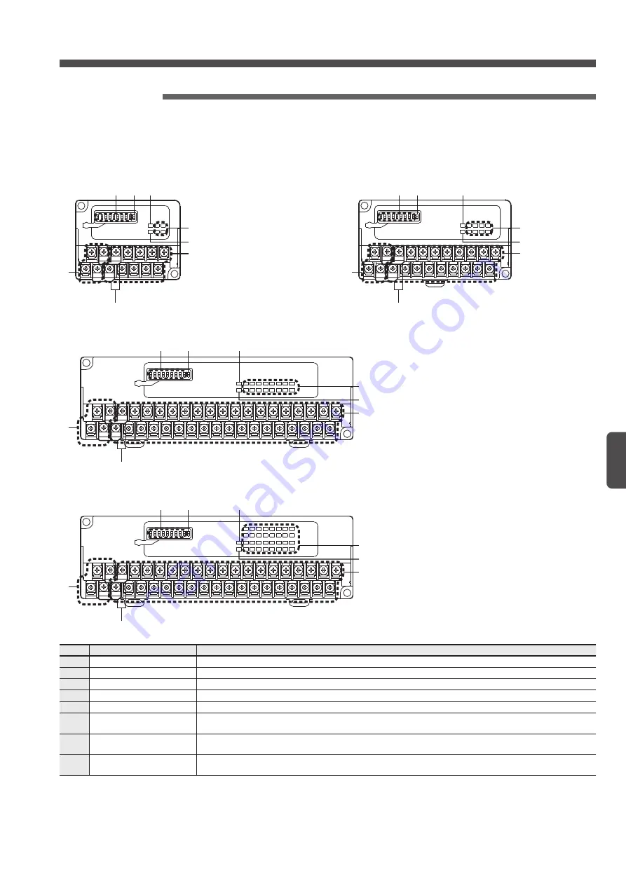
Input terminal
(
SL-VTB4
: 4-channel /
SL-VTB8
: 8-channel /
SL-VTB16
: 16-channel /
SL-VTB32
: 32-channel)
●
Part description
<SL-VTB8>
22
21
20
19
18
17
16
15
14
13
11
10
9
8
7
6
5
4
3
2
12
1
1
6
5
4
3
2
8
7
<SL-VTB4>
14
13
12
11
14
13
7
6
5
4
3
2
8
1
1
6
5
4
3
2
8
7
<SL-VTB16>
1
6
5
4
3
2
7
40
39
38
37
36
35
34
33
32
31
30
29
28
26
25
24
23
22
21
3
2
1
4
5
6
7
8
9
10
11
12
13
14
15
16
17
18
19
20
27
8
<SL-VTB32>
1
6
5
4
3
2
7
31
29
27
25
23
21
19
17
15
13
11
9
7
3
1
+
23
22
3
2
-
0
2
4
6
8
10
12
14
16
18
20
22
24
26
28
30
5
8
No.
Designation
Function
1
Input terminals
Used for connection of the input device.
2
Address setting switches
Used for setting of terminal address.
3
Not Used
Not used. (Setting to the OFF status is recommended.)
4
Power indicator (Green)
This indicator will light up when the power is supplied.
5
Input indicators (Green)
Each indicator will light up when the input signal of the corresponding channel is turned ON.
6
Transmission indicator
(Green)
This indicator will blink when the synchronization signal is sent from the
S-LINK V
controller.
7
Transmission cable con-
nection terminals
Used for connection of the
S-LINK V
system transmission cable.
To connect the local power supply unit, connect the cable to the +24V and 0V terminals.
8
Shorting piece
Used for shorting the line b24V and ‘+’ or between 0V and ‘-.’
Remove this piece to use different power supply units for the input device and the input terminal respectively.
Содержание S-LINK V
Страница 2: ...2 ...
Страница 5: ...5 Before Using This System ...
Страница 12: ...12 Before Using This System MEMO ...
Страница 13: ...13 Chapter 1 Designing System ...
Страница 35: ...35 Chapter 2 Wiring ...
Страница 60: ...60 Chapter 2 MEMO ...
Страница 61: ...61 Chapter 3 Starting System ...
Страница 71: ...71 Chapter 4 Specifications ...
Страница 161: ...161 Chapter 5 Troubleshooting ...
Страница 169: ...169 Appendix ...
Страница 180: ...180 Appendix MEMO ...


