Chapter 2
Getting Started — Connecting
60 - ENGLISH
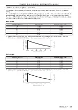
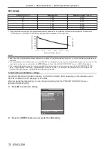
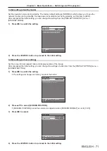
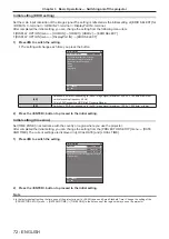
f
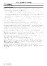
Do not pull cables forcefully. Also, do not bend or fold cables unnecessarily.
f
To reduce the effects of noise as much as possible, stretch out the cables between the twisted-pair-cable transmitter and the projector
without any loops.
f
Lay the cables between the twisted-pair-cable transmitter and the projector away from other cables, particularly power cables.
f
When laying multiple cables, run them side by side along the shortest distance possible without bundling them together.
f
After laying the cables, go to the [NETWORK] menu
→
[DIGITAL LINK]
→
[DIGITAL LINK STATUS] and confirm that the value of [SIGNAL
QUALITY] is displayed in green which indicates normal quality. (
x
page 196)
Note
f
For the HDMI cable, use an HDMI High Speed cable that conforms to the HDMI standards. If a cable that does not conform to the HDMI
standards is used, images may be interrupted or may not be projected.
f
The optional Digital Interface Box (Model No.: ET-YFB100G) and the optional DIGITAL LINK Switcher (Model No.: ET-YFB200G) do not
support the input and output of the 4K image signal.
f
The maximum transmission distance between the twisted-pair-cable transmitter and the projector is 100 m (328'1") for the signal with
resolution of 1 920 x 1 200 dots or less. For the signal with the resolution exceeding 1 920 x 1 200 dots, the maximum transmission distance
is 50 m (164'1"). It is possible to transmit up to 150 m (492'2") if the twisted-pair-cable transmitter supports the long-reach communication
method. However, the signal that the projector can receive is only up to 1080/60p (1 920 x 1 080 dots, dot clock frequency 148.5 MHz)
for the long-reach communication method. If these distances are exceeded, image may be disrupted or a malfunction may occur in LAN
communication. Please note that Panasonic Connect Co., Ltd. does not support the use of the projector outside the maximum transmission
distance. When connecting with the long reach, image signal or distance that can be transmitted may be restricted, depending on the
specification of the twisted-pair-cable transmitter.
f
For twisted-pair-cable transmitters of other manufacturers of which the operation has been verified with the projector, visit the following
website.
https://panasonic.net/cns/projector/
Confirmation of operation for the devices of other manufacturers has been performed with the items set independently by Panasonic
Connect Co., Ltd., and not all the operations are warranted. For operation or performance problems caused by the devices of other
manufacturers, contact the respective manufacturers.
Linking multiple displays devices
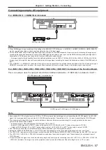
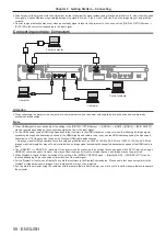
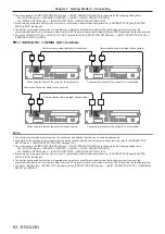
The <DIGITAL LINK OUT> terminal is a terminal to output DIGITAL LINK signal (including audio signal) input to
the <DIGITAL LINK IN/LAN> terminal.
By connecting multiple display devices (projectors or flat panel displays) supporting the DIGITAL LINK connection
in a daisy chain, it is possible to transmit image, audio, and serial control signals with a twisted pair cable.
DIGITAL LINK OUT
LINK
HDCP
POWER
LINK
HDCP
DIGITAL LINK IN
/
LAN
TY-SB01DL
DIGITAL LINK OUT
LINK
HDCP
POWER
LINK
HDCP
DIGITAL LINK IN
/
LAN
TY-SB01DL
Note
f
To transmit the Ethernet and serial control signals using the <DIGITAL LINK IN/LAN> terminal, set the [NETWORK] menu
→
[ETHERNET
TYPE] to [DIGITAL LINK] or [LAN & DIGITAL LINK].
However, only the first display device can received the Ethernet signal.
f
The DIGITAL LINK signal is output only when a display device (projector or flat panel display) that corresponds to any of the following is
connected to the <DIGITAL LINK OUT> terminal.
g
Panasonic Connect Co., Ltd. display device supporting the DIGITAL LINK input
g
Display device installed with the Panasonic Connect Co., Ltd. DIGITAL LINK Terminal Board supporting the DIGITAL LINK input
f
Up to 10 devices can be daisy chained. However, the image may not be displayed due to degraded signal quality depending on the
connected devices or the used cables.
f
Maximum number of connected devices is restricted to eight devices when inputting an image signal protected with HDCP 1.X.
f
Maximum number of connected devices is restricted to five devices when inputting an image signal protected with HDCP 2.X.
f
When the projector is in standby mode, the DIGITAL LINK signal input to the <DIGITAL LINK IN/LAN> terminal is not output from the
<DIGITAL LINK OUT> terminal.
Projector connecting terminals
Example of twisted-pair-cable transmitter
Projector connecting terminals
Содержание PT-REQ12 Series
Страница 63: ...ENGLISH 63 Chapter 3 Basic Operations This chapter describes basic operations to start with...
Страница 208: ...208 ENGLISH Chapter 5 Operations This chapter describes how to use each function...
Страница 266: ...266 ENGLISH Chapter 7 Appendix This chapter describes specifications and after sales service for the projector...

