


Chapter 1
Preparation — About your projector
38 - ENGLISH
Names and functions of the Function Board (optional)
This projector is equipped with Intel
®
Smart Display Module (Intel
®
SDM) specification slot.
Function Board supporting the Intel
®
SDM Small (Intel
®
SDM-S) or the Intel
®
SDM Large (Intel
®
SDM-L)
specification can be installed in the slot.
The terminal names of the optional Function Board with image input terminal to be used in this document is
defined here, and also their operations are explained. Also refer to the Operating Instructions of the Function
Board.
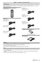
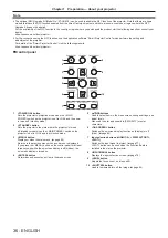
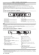
12G-SDI Terminal Board (Model No.: TY-SB01QS)
This board supports the HD-SDI signal, 3G-SDI signal, and 12G-SDI signal.
TY-SB01QS
1 IN
4 IN
3 IN
2 IN
OUT
3G SDI
12G/3G SDI
2
5
4
1
3
1 <SDI 4 IN> terminal
This is a terminal to input SDI signal (HD-SDI/3G-SDI).
2 <SDI 3 IN> terminal
This is a terminal to input SDI signal (HD-SDI/3G-SDI).
3 <SDI 2 IN> terminal
This is a terminal to input SDI signal (HD-SDI/3G-SDI).
4
<SDI OUT> terminal
This is an active through terminal to output the SDI signal
(HD-SDI/3G-SDI/12G-SDI) input to the <SDI 1 IN> terminal.
5
<SDI 1 IN> terminal
This is a terminal to input SDI signal (HD-SDI/3G-SDI/12G-SDI).
Note
f
The <SDI 2 IN> / <SDI 3 IN> / <SDI 4 IN> terminals are used when the quad link signal is input. These terminals do not support input of
12G-SDI signal.
f
When the projector is in standby mode, a signal is not output from the <SDI OUT> terminal.
f
This projector is not equipped with an audio function so it is not possible to output audio, but the audio signal input to the <SDI 1 IN>
terminal is output from the <SDI OUT> terminal.
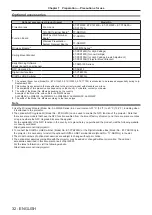
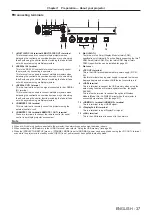
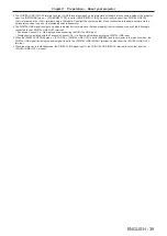
DIGITAL LINK Terminal Board (Model No.: TY-SB01DL)
This board supports the DIGITAL LINK signal.
DIGITAL LINK OUT
LINK
HDCP
POWER
LINK
HDCP
DIGITAL LINK IN
/
LAN
TY-SB01DL
5
2
3 4
3 4
1
1
Power status indicator <POWER>
On:
The power is supplied to the Function Board.
The [DISPLAY OPTION] menu
→
[SLOT IN]
→
[DIGITAL LINK
OUT] is set to [ENABLE].
Blinking:
The power is supplied to the Function Board.
The [DISPLAY OPTION] menu
→
[SLOT IN]
→
[DIGITAL LINK
OUT] is set to [DISABLE].
Off:
The power is not supplied to the Function Board.
2
<DIGITAL LINK OUT> terminal
This is a terminal to output DIGITAL LINK signal input to the
<DIGITAL LINK IN/LAN> terminal.
3
Signal status indicator <LINK>
On:
DIGITAL LINK signal is input or output.
Blinking:
Only the Ethernet signal is input or output.
Off:
DIGITAL LINK signal is not input or output.
4
Image signal indicator <HDCP>
On:
An image signal protected with HDCP is input or output.
Blinking:
An image signal that is not protected with HDCP is input or
output.
Off:
An image signal is not input or output.
5 <DIGITAL LINK IN/LAN> terminal
This is a terminal to connect a device that transmits an image
signal via the LAN terminal. Also, this is the LAN terminal to
connect to the network.
Note
f
To transmit the Ethernet and serial control signals using the <DIGITAL LINK IN/LAN> terminal, set the [NETWORK] menu
→
[ETHERNET
TYPE] to [DIGITAL LINK] or [LAN & DIGITAL LINK].
f
To transmit the Ethernet signal using the <LAN> terminal equipped on the projector as standard, set the [NETWORK] menu
→
[ETHERNET
TYPE] to [LAN] or [LAN & DIGITAL LINK].
Содержание PT-REQ12 Series
Страница 63: ...ENGLISH 63 Chapter 3 Basic Operations This chapter describes basic operations to start with...
Страница 208: ...208 ENGLISH Chapter 5 Operations This chapter describes how to use each function...
Страница 266: ...266 ENGLISH Chapter 7 Appendix This chapter describes specifications and after sales service for the projector...


