User Manual – ePX 200
OptiPro Systems, LLC.
Page 55 of 60
Last Modified: 7/30/2014
10.1.5
Checking Tram Ball Runout
1.
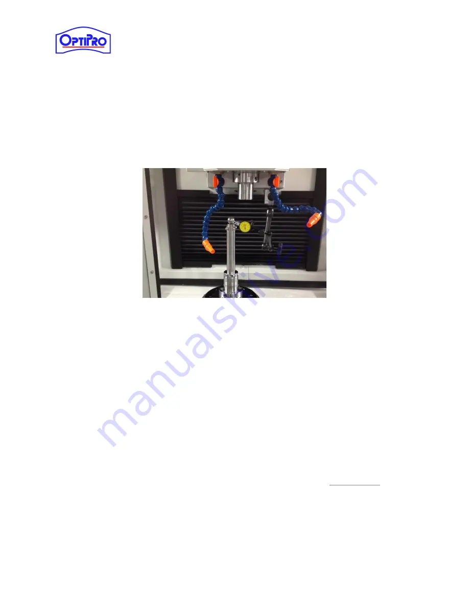
Thread the indicator base into the side of the tool spindle.
2.
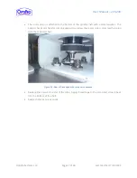
Install the long tram ball from the tram kit into the lower spindle. Align the indicator tip
parallel to the circumference of the ball.
3.
Zero the indicator gauge and rotate the lower spindle to check the existing runout.
4.
Use the four opposing socket head cap screws to adjust the ball until the runout of the ball
is less than 2µm. Remove the tram ball from the machine.
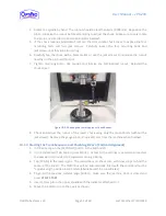
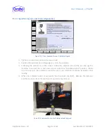
Figure 10-7: Checking Tram Ball Runout
10.1.6
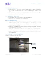
Finding Center of the B-Axis
1.
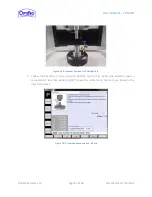
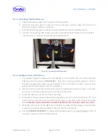
The Spindles Aligned position will automatically fill in the [MDI] box. Go to the Spindles
Aligned position by pressing
CYCLE START
. Using either the jog panel (see Section 5.2.1) or
the machine jog wheel, move the work spindle in the +Y direction until the Y-axis is at the
positive limit of its travel (closest to the operator).
2.
Insert the 10.25in tram ball into the lower chuck and tighten the actuation screw. The collar
on the tram ball shaft will bottom out on the face of the chuck.
3.
Screw the indicator arm into the side of the head.
4.
Using either the jog panel or the machine jog wheel, move the tool spindle to B +90°, and
then in the –Z direction until the center of the b-axis is near the center point of the tram
ball.
BE AWARE OF ANY MACHINE COLLISIONS BETWEEN THE TRAM BALL AND THE CHUCK.
5.
Place the indicator tip on the right side of the ball. Be aware that the travel in the indicator
may be much smaller than the offset of the tram ball from the B-axis.
6.
Set the
FEEDRATE OVERRIDE
to a safe and reasonable speed. Jog only the B-axis in the –B
direction. Keep track of the indicator travel.

