User Manual – ePX 200
OptiPro Systems, LLC.
Page 52 of 60
Last Modified: 7/30/2014
4.
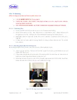
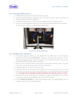
Rotate the spindle by hand. The runout should be less than 4µm (0.004mm). Reposition the
pin to minimize the runout before attempting to adjust the chuck. Make sure to only rotate
the pin in one direction to minimize indicator backlash.
5.
If the chuck requires adjustment, remove the tool spindle chuck cover to expose the four
mounting bolts and four jack screws. Carefully loosen the four mounting bolts and
jackscrews until they are all just snug.
6.
Carefully tap the chuck with a brass mallet or use the jack screws to minimize the runout
reading on the pin to within 2µm.
7.
Tighten mounting bolts. Use caution to minimize any bolt-induced runout. Reinstall the
chuck cover.
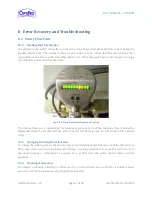
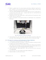
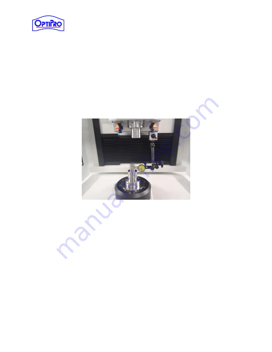
Figure 10-2: Checking the Lower Hydraulic Chuck Runout
8.
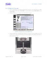
Check and adjust the runout of the lower chuck using only the mount bolts (without the
jackscrews). Remove the gauge pins and indicator arm from the machine when finished.
10.1.3
Starting the Tram Sequence and Checking B-Zero (Vertical Alignment)
1.
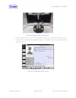
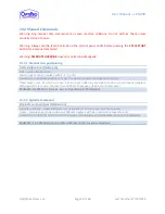
In P-Series, tap on the [SETTINGS] button in the bottom left.
2.
In the [Advanced] Tab, tap on [User Mode]. Access to the settings is password protected;
the password is provided to a supervisor during training.
3.
Tap [TRAM] in the lower right. The instructions on the screen will show steps to find the
center of the B-axis. The [MDI] box will be automatically filled with the command for the
“spindles align” position in G53 mode (absolute machine coordinates).
4.
To go to the previous spindles align position, make sure the machine door is closed and
press
CYCLE START
.
5.
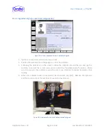
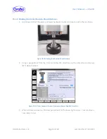
Insert a tram pin in the upper spindle with the indicator attached to it.
6.
Move the indicator tip to the c-axis as shown.

