User Manual – ePX 200
OptiPro Systems, LLC.
Page 42 of 60
Last Modified: 7/30/2014
8
Error Recovery and Troubleshooting
8.1
Slurry Flow Fault
8.1.1
Reading the Flow Monitor
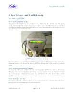
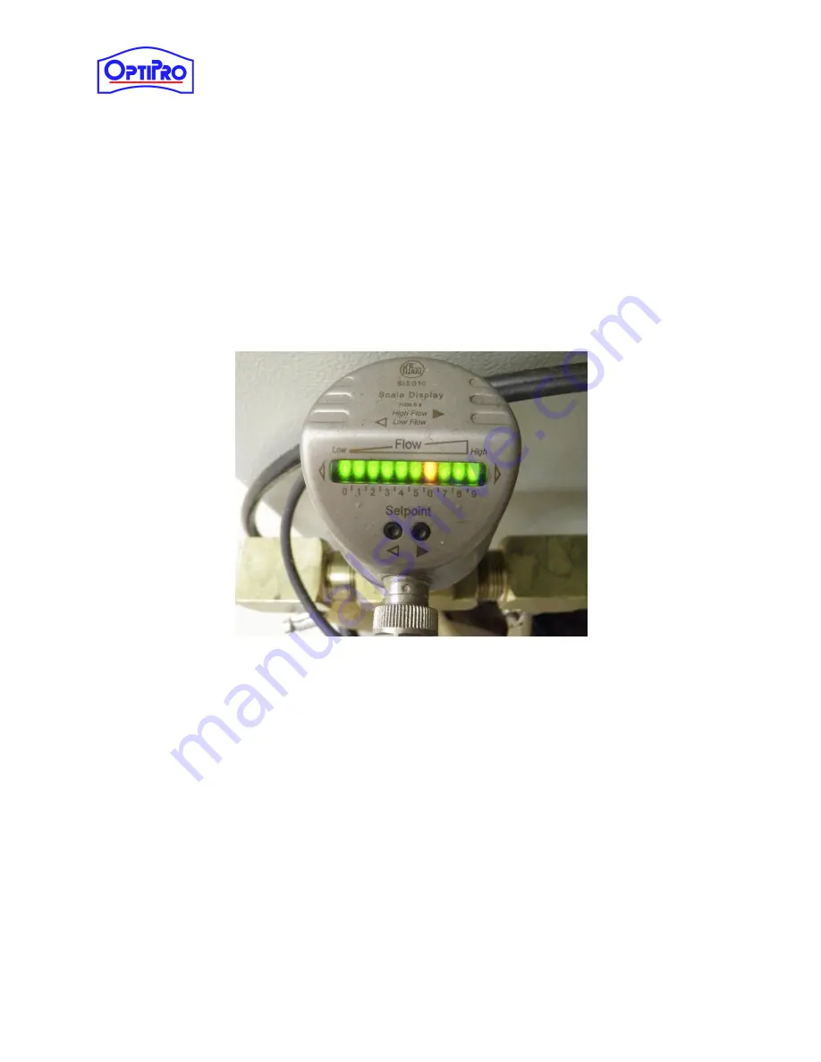
The display on the switch shows the current level of the flow and whether the flow is at or above the
predetermined level. The display is made up of a series of LEDs. When the flow level is lower than
required there will be a red LED called the switch point. When this switch point LED changes to orange
then the flow requirement has been met.
Figure 8-1: Slurry Flow Meter Display and Controls
The relative flow rate is indicated by the number of green LEDs lit. When the slurry flow is below the
displayable range the 1st LED will flash green. The last LED flashes green for a flow above the readable
range.
8.1.2
Changing the Required Flow Rate
To change the switch point on the monitor press and hold either Setpoint button until the LED starts to
flash, the buttons are found just below the display. Use the pushbuttons to move the switch point to
the desired location. After about 2 seconds of no activity then the switch should resume normal
operation.
8.1.3
Cleaning if Necessary
The switch can develop a build-up on the sensor tip. To clean the tip, use a soft cloth. If stubborn build-
up exists, it should be removed using vinegar based cleaner.

