


78
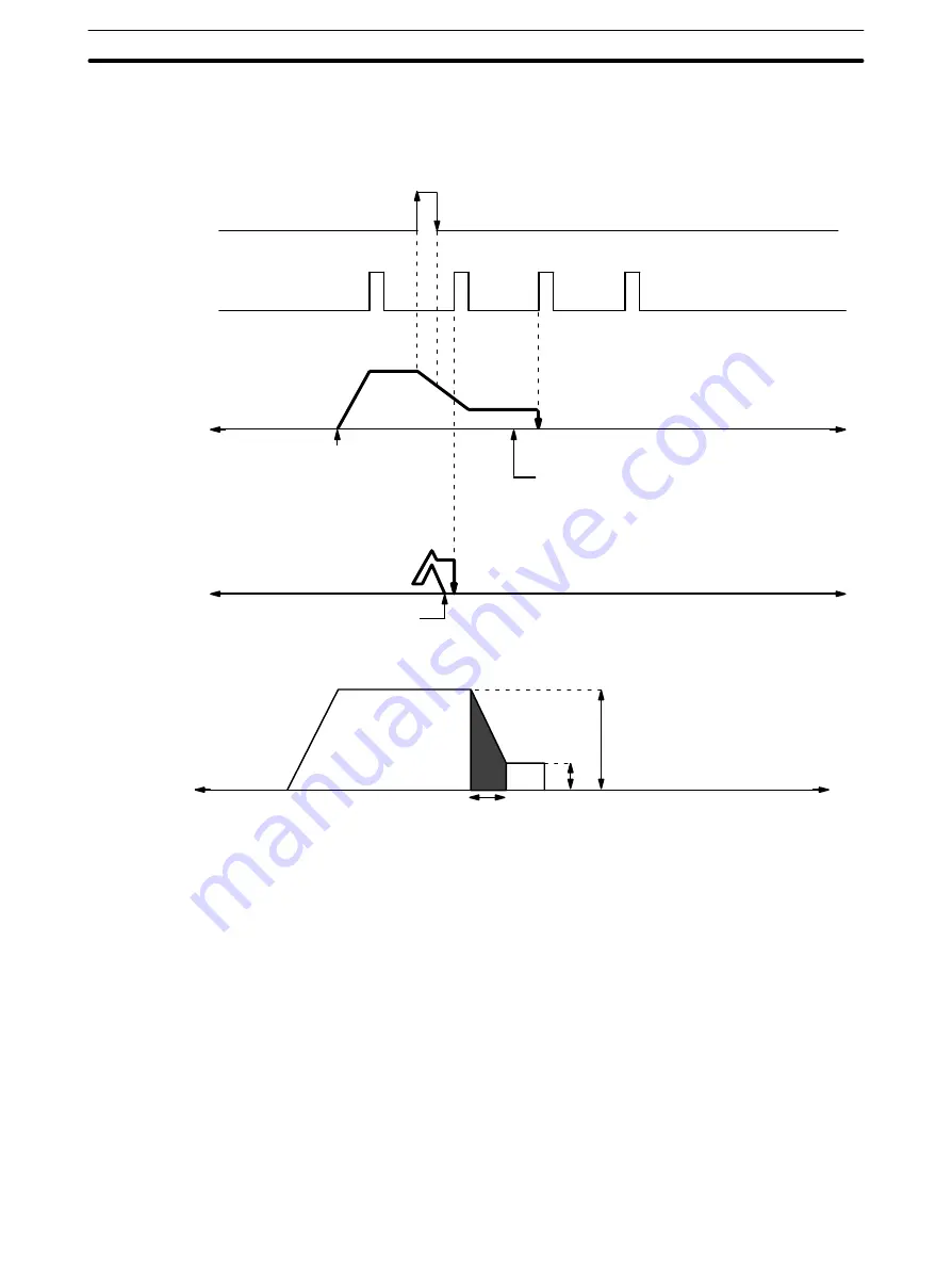
tect a different origin signal. Therefore, be sure that the origin proximity signal
period is long enough, i.e., at least as long as the deceleration period. The
following diagram shows what can happen if this is not done.
Origin proximity
signal
Origin signal
Pulse output
1
0
1
0
CCW
CCW
Ideal position for origin proximity
signal to turn OFF
Positioning axis
CW
Positioning axis
CW
ORIGIN SEARCH (Start)
Origin (Stop)
Deceleration Time Calculations
Pulse output
T
D
V
L
V
H
Positioning axis
CW
CCW
Deceleration time:
T
D
= V
H
– V
L
/1000 x R
where
R is deceleration data (pps/1 ms)
Number of pulses for deceleration period:
P
D
= (V
H
+ V
L
) x T
D
/2
= V
H2
– V
L2
/2000 x R
For example, where V
H
= 20000 pps, V
L
= 1000 pps, and R = 1000 pps/ms,
P
D
= 20000
2
– 1000
2
/2000 x 100
= 1995
Therefore, approximately 2,000 pulses are required for deceleration.
In this example, origin proximity reverse is not used. DIP switch pin 3 is ON
and pin 8 is OFF. Positioning is stopped when the first origin signal has been
input after deceleration has ended.
Example 2:
When Origin Proximity
Reverse is Disabled
ORIGIN SEARCH


