


56
4.
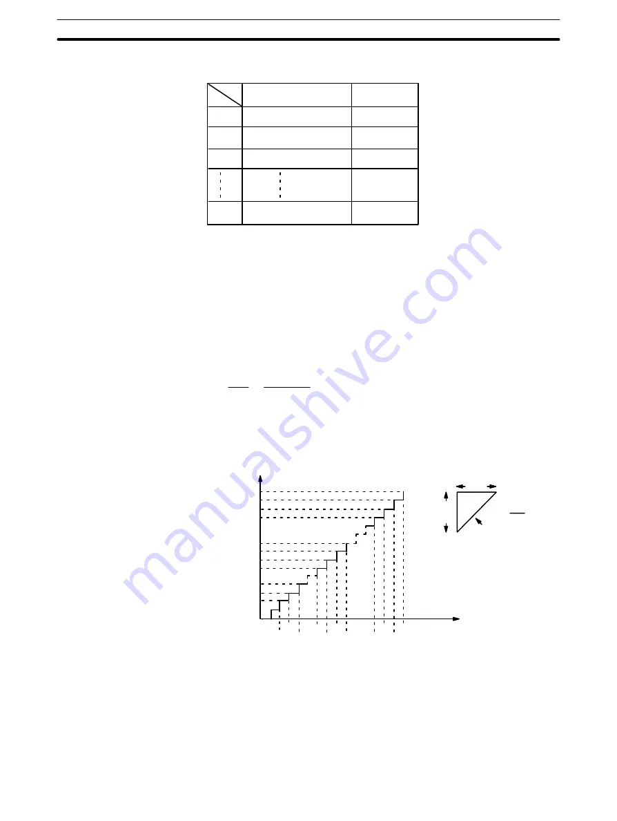
The divider ratios for all steps are calculated and set in a table.
Step
Target (step) speed
Divider ratio
1
MIN
2
MIN +
∆υ
3
MIN + 2
∆υ
L
MAX
5.
Example
Start speed
0 (pps)
Maximum value of speed data Nos. 1 to 15
20000 (pps)
Acceleration
100 (pps/1ms)
Deceleration
100 (pps/1ms)
∆υ
= 40000/100 = 400
∆
V = 20000 x 2 = 40000
L = (
∆
V/R) = (40000/100) = 100
4
4
4
8
12
192
196
200
204
388 396
392 400
t (Time)
ms
V (Speed)
400
4 ms
R = 400= 100
4
40000
39600
39200
38800
20400
20000
19600
19200
1600
1200
800
400
pps
The time required between START command bit recognition and the begin-
ning of pulse output is 0.1 second or less.
Only about 10 ms is required to begin execution of positioning actions with
“single” completion codes.
The time required between CHANGE SPEED or STOP command bit recogni-
tion and the beginning of execution is at least 4 ms.
START Activation Time
External Interrupt
Response Time
DM Area Allocation


