


8
Positioning pulse
1 2 n
Positioning output
Angle of
rotation
Angle of rotation
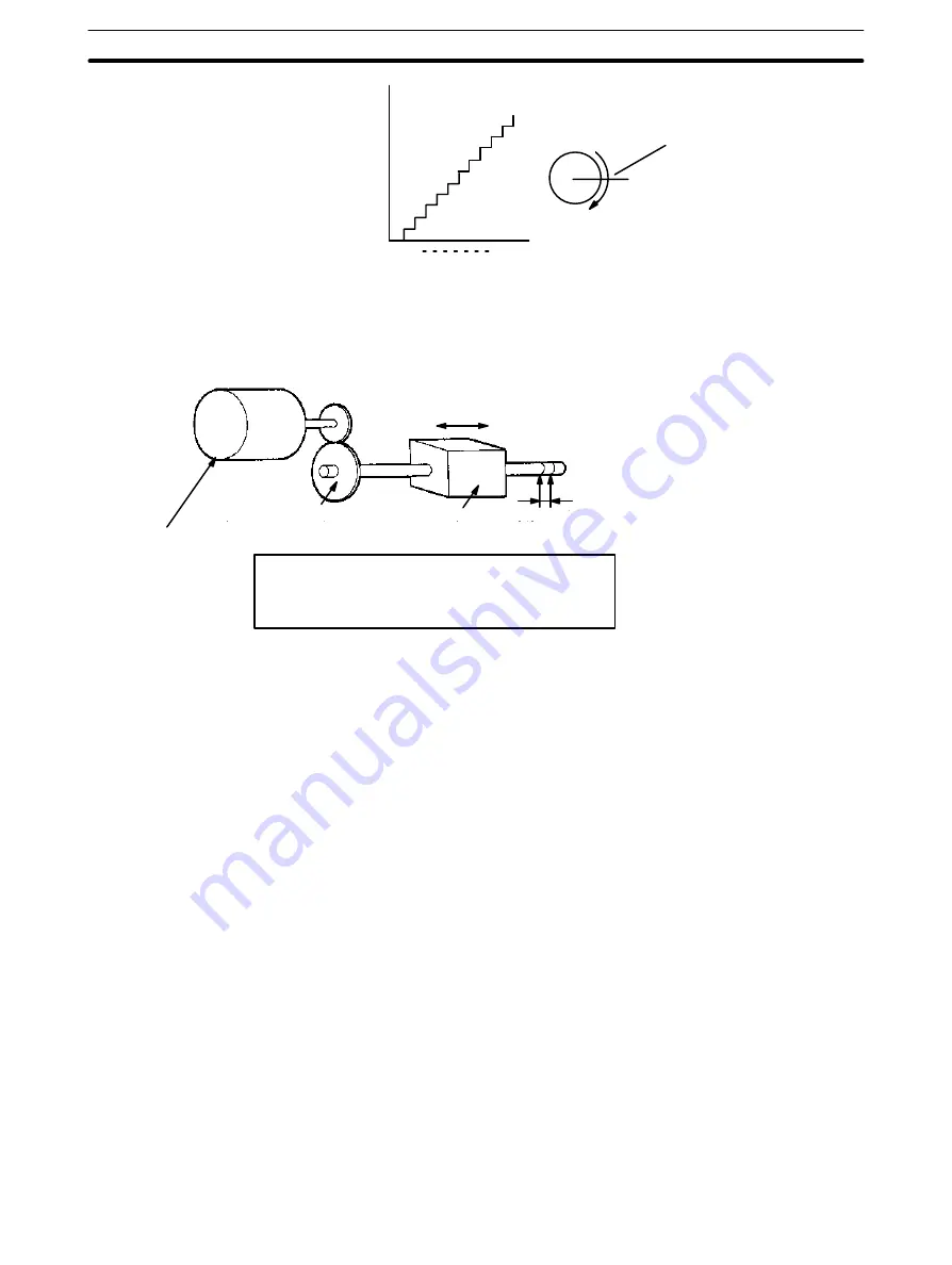
The following diagram and parameters illustrate a simplified positioning sys-
tem.
P
Stepping motor
Reduction gear
Object being
positioned
M: Reduction ratio
P: Feed screw pitch (mm/revolution)
V: Feed velocity of object being positioned (mm/s)
S
: Stepping angle per pulse (degree/pulse)
M
V
Feed screw pitch
S
The positioning accuracy in mm/pulse is computed as follows:
Positioning precision = P/(pulses per revolution x M)
= P/((360/S) x M))
= (P x S)/(360 x M)
The required pulse frequency from the Unit in pulses per second is computed
as follows:
Pulse frequency = V/Positioning precision
= (360 x M x V)/(P x S)
The required number of pulses to feed an object by a distance L (in mm) is
computed as follows:
Number of pulses = L/Positioning precision
= (360 x M x L)/(P x S)
1–5–2
Semiclosed-loop System
When the Position Control Unit is used in a semiclosed-loop system, the sys-
tem supplies feedback which is used to compensate for any discrepancy be-
tween target values and actual values in position or speed. This system de-
tects motor rotation amounts, for example, computes the error between the
target value and actual movement value, and zeroes the error through feed-
back. The diagram below illustrates the basic configuration of a semi-
closed-loop system.
Simplified Positioning
System Design
Positioning System Principles


