


SERVICING THE UNIT
Caution:
Disconnect power before servicing this
appliance.
Caution:
Label all wires prior to disconnection
when servicing controls. Wiring errors can cause
improper and dangerous operation.
The combustion chamber, heat exchanger and
flue baffles are all fabricated from stainless steel and
do not require cleaning.
Should the main burner fail to light, or flame is not
detected during the first trial for ignition period, the gas
valve is de-energized and the control goes through an
interpurge delay before another ignition attempt. The
control will attempt two additional ignition trials before
going into lockout. The valve relay will be
de-energized immediately, and the combustion blower
will be turned off.
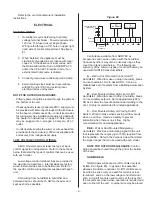
FAULT CONDITIONS
This appliance is equipped with a self diagnostic
ignition module which identifies a fault code when it
occurs.
B and P Models
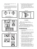
Faults are indicated with a flashing LED on B and
P units. The LED’s are located on the switch panel
and correspond to their respective ignition modules
from left to right looking from the burner entry side.
Counting the number of flashes of the LED’s and
referring to the Fault Conditions given below can
identify most ignition problems. Recovery from lockout
requires resetting of the humidifier. Momentarily shut
off the power switch, then turn it back on again.
B/P Remote Fault Indiction
On GHB / P units, the remote fault alarm options
allow warning and errors to be via set of dry contact at
the humidifier.
MC MODELS
Faults are indicated with a fault message on the
display of MC models. Refer to “GHMC Display Unit
Operating Instructions” (Form #XX-274) for an
explanation of fault messages. Recovery from lockout
requires resetting of the humidifier. This can be
achieved by momentarily shutting off the power switch
then turning it back on, or by pressing the reset button
on the main MC control board mounted on the
Electrical Swing Panel inside the electrical cabinet.
Remote Fault Indication Option MC Model
The unit operating status is signaled via the
indicator lamps on the humidifier and via the operating
and remote fault alarm, as follows:
Operating
status /
mean
Indication on
Unit
Activated
remote display
relay
Warning
(Humidification
continuing) or error
(Humidification off)
Red lamp lights
(Error)
Security loop open (on/
off relays)
Yellow lamp
lights
(Security loop)
Unit receiving
demand signal
Green lamp
lights
(Humidity
demand)
Set maintenance inter-
val has expired
Red lamp flashes (Maintenance)
SERVICE CHECKS
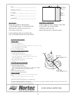
Flame Sensor
Flame current is the current which passes through
the flame from the sensor to ground. The ignition
module must detect a minimum flame current of 0.7
microamps or a flame proving lockout will occur. To
measure flame current, connect an DC micrometer to
the FC- FC+ terminals on the module. Meter should
read 0.7 uA or higher. If meter reads below “0” on
scale, meter leads are reversed. Disconnect power
and reconnect meter leads for proper polarity.
NOTE:
Proper polarity of supply voltage to the
unit is necessary for flame sensing to occur.
NOTE:
Oxidation on flame sensing rod can
reduce measured current. The oxidation can be
cleaned from the sensing rod using steel wool or an
emery cloth.
- 23 -
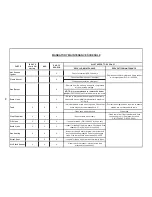
Error Mode
LED Indication
Internal Control Failure
Steady on
Air Flow Fault
1 Flash
Flame With No Call For Heat 2 Flashes
Ignition Lockout
3 Flashes
Содержание GH 100
Страница 43: ... 39 ...