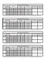
manufacturer listing, see page 28. Contact NORTEC
for additional information.
Class B vent must
not
be used. Class “BH” vent
must be used based on list of approved manufacturers
shown in the installation manual.
GH100 exhaust manifold terminates with 3”O.D.
Stainless Steel Tubing. GH200, 300 and 400 exhaust
manifolds terminate with 4”O.D. Stainless Steel
Tubing.
The maximum flue gas temperature at the
humidifier vent connector will not exceed 480°F. Use
only special gas vents listed for use with Category III
or IV gas burning appliances, such as those listed in
the venting system chart, see page 28. (Listed to UL
Standard 1738 in the USA and ULC-S636 in Canada.)
All venting joints must be positively sealed with
high temperature RTV silicone sealant rated for at
least 480°F.
Operating Venting Temperature
Normal
Maximum
All GH
360-380°F
(182-193°C)
450°F
(232°C)
When venting a category IV appliance it is
necessary to provide for condensate removal in the
venting system. This provision may be met by using
the special drain tee as listed in the venting system
chart.
When a drain tee is used it is necessary to install a
trap in the drain to ensure that flue gases do not vent
into the drain. Install the trap with a 12” minimum
height of standing water column.
Install the trap a minimum of 12” below flue vent
with a depth minimum of 3”.
Prior to activating the appliance, ensure that the
trap is filled with water and that the drain terminates in
accordance with local plumbing codes.
For any vent lengths over 20 feet long, use
insulated vent. Also provide condensate removal in
the venting system.
WARNING:
Provide a screen or barrier to prevent
personal injury in areas where inadvertent personnel
contact with vent pipe can occur.
Standard Unit
The maximum recommended vent length is 100
equivalent feet where each 90° elbow equals 10' and
each 45° elbow equals 5'. For lengths over 100’,
consult factory.
Direct Vent Unit
A maximum exhaust vent length of only 70
equivalent feet (21m) is permitted with the direct vent
option, where each 90º elbow equals 10ft and each
45º elbow equals 5ft. This maximum cannot be
exceeded.
All horizontal runs of the vent pipe shall have a
minimum rise of 1/4” per foot (21 mm/m) and shall be
supported at maximum intervals of 5' (1.5 m) and at
each point where an elbow is used.
The vent terminal must be installed within the
same atmospheric pressure zone as the combustion
air inlet of the humidifier.
Periodic cleaning of the screens in the vent
terminal is required for proper operation of the
humidifier.
NOTE OUTDOOR ENCLOSURE:
Flue gases
must be vented out of the enclosure.
ADDITIONAL REQUIREMENTS WHEN VENTING
THROUGH A SIDEWALL
For sidewall venting, locate the humidifier as close
as possible to the wall being used.
Locate the vent terminal at least three feet above
any forced air inlet located within ten feet; or at least
four feet below, four feet horizontally from, or one foot
above any door, window, or gravity air inlet into any
building.
A minimum horizontal clearance of four feet from
electric meters, gas meters, regulator and relief
equipment is required.
Locate the vent terminal at least seven feet above
grade when it is adjacent to public walkways.
Locate the bottom of the vent terminal at least
twelve inches above grade or ground, or normally
expected snow accumulation level. The snow level
may be higher on walls exposed to prevailing winds.
Avoid areas where local experience indicates that
condensate drip may cause problems such as above
planters, patios, or over public walkways, or over an
area where condensate or vapor could create a
nuisance or hazard, or could be detrimental to the
operation of regulators, relief valves, or other
equipment.
- 8 -
Содержание GH 100
Страница 43: ... 39 ...

