background image

- 35 -

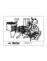
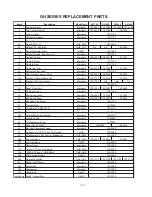
GH SERIES REPLACEMENT PARTS

Item #

Description

Model Type

GH 100

GH 200

GH 300

GH 400

1

Knob, Tank lid -Hold down

all models

2

Tank Lid

all models

170-5010

170-5012

170-5014

170-5014

3

Gasket, Tank Lid

all models

170-8201

170-8210

4

Gasket, Exhaust manifold

all models

170-8215

150-1653

5

Exhaust Assembly

all models

170-5038

170-5044

6

Sensor, Stack Hi-Limit Manual Reset

all models

7

Fill Cup Assembly

all models

8a,b

Hose Kit - Fill Valve Lines

all models

9a,b,c,d

Hose Kit - Drain Pump and DWC

all models

10a,b

Hose Kit - Float Chamber to Tank

all models

11

Dual Fill Valve

all models

170-4231

170-4232

150-1357

170-4234

12

Float Chamber Dual Fill

all models

13

Float Chamber Bracket

all models

14

Float Chamber Board

all models

15

Pump, Drain 24V 60Hz

all models

16

Drain Water Cooler Valve Assembly

all models

17

Drain Water Cooler Body Assembly

all models

18

Ignition Module (all Burners)

GHMC

Ignition Module, Main (Burner A only)

GHB, GHP

Ignition Module, Auxiliary (Burners B, C, D)

GHB, GHP

n/a

19

Switch, Air Proving, 0.2"w.c. differential

regular models

Switch, Air Proving, 0.45"w.c. differential

direct vent models

20

Bracket, Ignition Control

all models

21

Igniter, Hot Surface Shielded with gasket

all models

22

Sensor, Flame Proving with gasket

all models

23

Gasket, Burner plate

all models

not shown Flame Sensor / Ignitor Kit

all models

24

Burner Assembly

all models

24a

Burner Assembly complete

all models

25

Gasket, Igniter (Shielded)

all models

26

Sight Window Replacement Kit

all models

27

Gas Valve/Venturi, 36kW

all models

27a

Elbow Assembly, Air Intake Adapter

all models

27b

Gasket, Blower/CVI air intake

all models

28a

Blower 24V dc, with CVI

all models

28b

Gasket, Blower/Burner

all models

29

Manifold, Gas Intake

all models

150-4187

150-4188

30

Removable Heat Exchanger

all models

30a

Seal Plate for GH 300 only (not shown)

all models

n/a

n/a

150-2002

n/a

31

Gasket, Heat Exchanger

all models

32

Tank Weld Assembly with insulation

all models

150-3881

150-3882

33

Direct Vent - Air Manifold

all models

150-2030

150-2029

150-2320

150-1634

34

Direct Vent - Hose, Flexible Connector

all models

35

Direct Vent - Clamp, Gear

all models

170-8208

150-4190

170-5015

150-3884

150-4191

150-4204

150-4172

150-4174

150-4182

150-4202

170-8220

150-3883

150-2148

132-5009

170-8219

150-4031

170-5861

170-9601

150-3886

170-8206

170-2501

170-2502

150-4175

150-2166

150-2644

150-3100

150-3089

170-2502

150-4442

150-3031

150-2647

150-3810

170-3202

150-4039

150-4443

150-4444

170-8828

170-8214

150-1654

170-5048

Содержание GH 100

Страница 1: ... supplier s instructions If you can not reach your gas supplier call the fire department WARNING Improper installation adjustment alteration service or maintenance can cause injury or property damage Refer to this manual For assistance or additional information consult a qualified installer service agency or the gas supplier WARNING If the information in this manual is not followed exactly a fire ...

Страница 2: ...ADDITIONAL REQUIREMENTS WHEN VENTING THROUGH A SIDEWALL 8 ELECTRICAL 9 PRIMARY WIRING 9 LOW VOLTAGE CONTROL WIRING 9 CONTROL INSTALLATION 10 OUTDOOR ENCLOSURE HEATER SETTING 10 BLOWER PACKS 10 STEAM DISTRIBUTORS FOR DUCTED APPLICATIONS 10 PLUMBING 12 FILL WATER SUPPLY LINE 12 DRAIN LINE 13 DRAIN WATER COOLER SUPPLY LINE 13 STEAM LINE 14 WATER TRAP 15 CONDENSATE RETURN LINES FOR STEAM DISTRIBUTORS ...

Страница 3: ...TMENTS REPLACEMENTS OF COMPONENTS 20 GAS VALVE REPLACEMENT 20 HOT SURFACE IGNITER REPLACEMENT 20 IGNITION MODULE REPLACEMENT 20 TRANSFORMER REPLACEMENT 20 AIR SWITCH REPLACEMENT 21 DRAIN PUMP REPLACEMENT 21 COMBUSTION AIR BLOWER REPLACEMENT 21 TANK REPLACEMENT 21 HEAT EXCHANGER REPLACEMENT 22 SERVICING THE UNIT 23 FAULT CONDITIONS 23 B AND P MODELS 23 MC MODELS 23 SERVICE CHECKS 23 FLAME SENSOR 23...

Страница 4: ... GH ENCLOSURE PHYSICAL DATA 32 GH ENCLOSURE HEATER INSTALLATION INSTRUCTIONS 33 REPLACEMENT PARTS 34 37 MAINTENANCE CHART 38 ...

Страница 5: ...g inspect equipment for damage and if damage is found notify the shipper promptly 5 All NORTEC products are shipped on an F O B factory basis Any and all damage breakage or loss claims are to be made directly to the shipping company GENERAL SPECIFICATIONS The NORTEC GH Series humidifier is a completely new patented design based on leading edge technology The GH is designed to provide clean steam h...

Страница 6: ...PUT BTUH STEAM CAPACITY LBS HR MANIFOLD PRESS IN W C SHIPPING WEIGHT LBS OPERATING WEIGHT LBS STD DV STD DV NATURAL GAS MAX 238 000 238 000 200 200 0 05 350 660 MIN B P 120 000 120 000 100 100 0 05 MIN MC 40 000 60 000 25 50 0 05 PROPANE LP GAS MAX 238 000 238 000 200 200 0 05 350 660 MIN B P 120 000 120 000 100 100 0 05 MIN MC 48 000 60 000 30 50 0 05 MODEL GH 300 SPECIFICATIONS FUEL BLOWER SPEED...

Страница 7: ...combustible material The humidifier shall not be installed directly on carpeting tile or other combustible material other than wood flooring 8 For recommended clearances for servicing refer to Figure 2 9 During installation cover the humidifier to prevent any dust or other contaminants from entering the cabinet when activities such as drilling are taking place NOTE Some insulating materials may be...

Страница 8: ... in the back of the cabinet so that the unit cannot be bumped off the wall bracket See Figure 3 7 Make sure humidifier is mounted level If floor mounted adjust using leveling legs All GH models are equipped with adjustable leveling legs which have a maximum travel of 1 5 These legs may be used to allow mounting of an optional stand These legs may be removed and replaced by longer legs Factory appr...

Страница 9: ...or exhaust system also see local code 3 The enclosure should be bolted down or secured if it is to be exposed to high winds 4 If lifting the enclosure on the roof using a forklift lift under the unit at cross members for stability Strapping belts can also be used 5 Clearances around the unit should also be maintained for good access to the gas humidifier 3 feet of clearance is needed on the right ...

Страница 10: ... FOR OUTDOOR ENCLOSURE Gas lines should be routed through the bottom of the enclosure NOTE FOR DIRECT VENT UNITS The combustion supply air opening is not required to the room where the appliance is installed since the combustion air will be provided through the inlet air duct see installation notes below Ventilation is required for cooling of the electronic components AIR MANIFOLD CONNECTOR HOSE I...

Страница 11: ...ount the intake duct over the connector and secure with an appropriate clamp to ensure a proper seal has been achieved TERMINAL LOCATION The intake duct must terminate at an outside location with the supplied vent terminal The intake and vent terminals must be installed as shown in Figure 7 When locating the intake terminal a minimum distance must be maintained from the exhaust vent terminal to pr...

Страница 12: ...e maximum recommended vent length is 100 equivalent feet where each 90 elbow equals 10 and each 45 elbow equals 5 For lengths over 100 consult factory Direct Vent Unit A maximum exhaust vent length of only 70 equivalent feet 21m is permitted with the direct vent option where each 90º elbow equals 10ft and each 45º elbow equals 5ft This maximum cannot be exceeded All horizontal runs of the vent pip...

Страница 13: ...umidistat to humidifier and between devices should be 18 AWG or heavier and kept as short as possible Controls are available from NORTEC as accessories and can be ordered with the humidifier Controls by others may also be used as long as they meet the criteria noted below The following is a summary of the common types of controls that may be used with NORTEC Gas Humidifiers A Wall or Duct Mounted ...

Страница 14: ... front of steam distributor or in turbulent or mixing zone Mount humidistat where air s humidity and temperature are uniform and representative of spaces being humidified 3 Mount duct high limit humidistat downstream of steam distributors far enough that under normal humidity and air flow conditions steam will have been fully absorbed typically at least 10 feet It must be located to sense high hum...

Страница 15: ... require the unit to be fitted with an extended external water trap Consult factory 7 Low temperature ducts below 60 F 15 C shallow ducts or branch ducts might require the use of a field supplied condensate drain pan below the steam distributor See Figure 10 8 The steam distributor mounting plate is perpendicular to the steam distributor When the mounting plate is attached to the side of the duct ...

Страница 16: ...intended to operate on cold potable tap water 2 DO NOT use a hot water source to supply the humidifier Minerals will adhere more easily to surfaces and the fill valve s small flow regulating orifice could become plugged 3 Consider using a water softener Longer operating times between tank cleaning will be reached on softened water 4 Reverse osmosis RO water can provide very long times before clean...

Страница 17: ...re available refer to Engineering Manual Form XX 261 if an appropriate drain is not available 3 Keep drain lines as short as possible Keep drain lines sloped down not level and not up since low spots in drain lines will accumulate sediment and cause backup The drain line should be 1 3 4 O D or larger Drain water is tempered to be below 60ºC so any kind of plumbing tubing may be used Consult local ...

Страница 18: ...e the length of steam line and keep it as straight as possible minimizing bends Avoid using 90 elbows Wherever possible use long radius turns using tube bender on oversized copper or pairs of 45 elbows This will reduce the condensate generated by heat loss This will also reduce the back pressure and avoid the need to install an extended water trap 5 Ensure that the steam hose does not kink or sag ...

Страница 19: ...ferential that develops in the built in water trap 3 The built in water trap allows a maximum of 4 5 W C pressure before tank water escapes through drain This pressure should not be exceeded 4 Static pressure is usually higher when distributor s steam outlets are faced upstream in a duct CONDENSATE RETURN LINES FOR STEAM DISTRIBUTORS 1 Nortec steam distributors and blower packs have built in conne...

Страница 20: ...fills the water tank When the water level reaches switch C see Figure 26 the firing sequence will be initiated The water fill continues until switch B is reached While the water level is between switch A and B the fill valve will be pulsed for intervals proportional to the demand for humidity When the water level reaches switch A the fill valve will be disabled 60 seconds after the fill valve is d...

Страница 21: ...s necessary to wait for all blowers to cycle 3 After seven seconds the gas valve is energized for four seconds then de energized After three trials for ignition complete with pre purge the unit goes into a safety lockout 4 Manually re open the gas supply No gas should flow to the main burner End of test 5 To reset the system momentarily shut off power switch then turn it back on again After a pre ...

Страница 22: ...rom NORTEC If you are unaware of the hardness or silica content of your water supply there are many do it yourself kits which can be purchased or there are several companies that will perform the tests for a reasonable price You can even contact your municipality for your water condition It is possible to reduce this setting according to observation and guidelines in the tables above Also when hig...

Страница 23: ...lines and remove cabinet lid Lid is held down by keyed lock at rear lip Remove tank lid by removing hold down knobs or nuts being careful to not damage the insulation or gasket Do not remove the heat exchangers without consulting NORTEC Scoop out loose scale with a small shovel such as those used for gardening Once loose scale is removed use a scraper such as a plastic windshield scraper to remove...

Страница 24: ...nents Gas Valve Replacement 1 Shut off electrical power and gas supply to the appliance 2 Remove front door and right side panel 3 On units with multiple burners disconnect gas supply line from the Gas Intake Manifold On units with a single burner disconnect the gas supply line from the gas valve 4 Disconnect wiring connections to gas valve 5 Disconnect hoses at air proving switch 6 Remove entire ...

Страница 25: ...appliance 2 Remove front door and right side panel 3 Disconnect electrical plug connection to blower motor 4 Disconnect the pressure hoses at the air proving switch 5 Remove gas train with gas valve venturi assembly as described in Gas Valve Replacement section on page 19 6 Remove nuts 4 on discharge outlet of blower 7 Remove blower 8 Attach gas valve venturi assembly onto new combustion blower en...

Страница 26: ...e Tank 2 2 Switch off power to the unit and open front and right doors 3 3 Shut off gas supply to the unit 4 4 Remove gas train as described under Gas Valve Replacement on page 19 5 5 Disconnect wire harness at blower ignition module air proving 6 6 Disconnect vent connection to the unit 7 7 Remove exhaust manifold 8 8 Remove heat exchanger nuts 9 9 Slide heat exchanger out 10 10 Re assemble in re...

Страница 27: ...o GHMC Display Unit Operating Instructions Form XX 274 for an explanation of fault messages Recovery from lockout requires resetting of the humidifier This can be achieved by momentarily shutting off the power switch then turning it back on or by pressing the reset button on the main MC control board mounted on the Electrical Swing Panel inside the electrical cabinet Remote Fault Indication Option...

Страница 28: ...e igniter is okay otherwise it should be replaced Gas Valve Setting The gas valves used in the GH series humidifier are negative pressure regulated valves The valve setting listed on the product rating plate is shown relative to atmosphere this setting will always remain constant In the direct vent application the actual manifold outlet pressure of each gas valve will vary depending on the vent le...

Страница 29: ...pply defective or fuse blown Check fuse on power supply Power to unit on humidistat on indicator lights on except humidity demand Control signal miswired Check signal Low water level Check water supply Low float switch stuck or defective Check continuity of float switch and inspect floats Clean floats if scaled up replace if defective Bad control Check LED for steady on or check MC display Pressur...

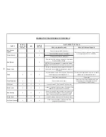
Страница 30: ... Float Chamber X X X Ensure floats move freely Clean scale from float chamber and hose connecting to hit Replacement hose P N 150 4443 P N 150 4442 Fill Lines X X X Inspect for leaks P N 150 4443 for hose set Drain Lines X X X Inspect for leaks at the drain pump fill cup and float chamber P N 150 4444 for hose set Gas Venting X X X Inspect for leaks Ensure terminal cap is clear and any condensatio...

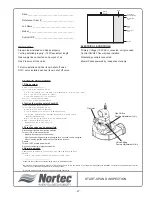
Страница 31: ...fter 7 seconds the gas valve will energize for 4 seconds the de energize After 3 tries the ignition module will go into safety lockout Repeat Turn unit OFF at main power switch Re connect all igniters to ignition modules 4 Normal operation Reset system by momentarily shutting OFF main power switch and switching back ON Igniter will start to heat up and normal operation cycle will occur ___________...

Страница 32: ... 4803 E mail sales heat fab com Female Female Adapter 3 FSA NOR 3 4 FSAA4 Please call or see their website to locate the wholesaler closest to you FAS N SEAL www protechinfo com fasnseal html Telephone 800 766 3473 Fax 518 463 5271 E mail sales protechinfo com Female Female Adapter 3 FSAA3 4 FSAA4 Please call or see their website to locate the wholesaler closest to you Z FLEX www flexmaster com zf...

Страница 33: ...eripheral Humidifier Interface 0 10 Vdc INPUTS OUTPUTS NOTE This is a wiring diagram only For specific wiring instructions it is necessary to refer to the wiring diagram which is supplied with each unit generic 1 2 MC Models Only On Off Control Humidistat Air Proving Switch High Limit Humidistat Blower Pack Other On Off Device NOTE If no On Off Control is used then a field jumper must be connected...

Страница 34: ...F Controls in series Field wiring for GHB ON OFF By others 1 2 3 4 5 6 ON OFF Controls in series Field wiring for GHP 0 10 Vdc Modulation By Others 0 10 Vdc Modulating Humidistat By Others Wall Or Duct GH B P Wiring Diagram ...

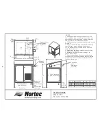
Страница 35: ...24 LOCK WASHER 3 8 NUT U N COARSE 3 8 BOLT 3 8 16 x 3 4 DETAIL A H L W GH STANDS SHOP DRAWING Part Model L in cm in cm in cm 150 2412 GH 100 12 6 32 26 4 67 30 0 77 150 2413 GH 200 20 3 52 23 8 61 30 0 77 150 2414 GH 300 400 36 7 94 23 8 61 30 0 77 MODEL DIMENSION ...

Страница 36: ...de at site by others 3 See GH Shop Drawings for dimensions locating vent fill drain steam and gas connections 4 As a standard the GH unit is factory mounted inside the enclosure 5 Steam lines should be routed through the back or sides of the enclosure 6 Insulate and minimze steam run length to reduce steam losses 7 If freezing conditions occur enclosure should be used in conjunction with freeze pr...

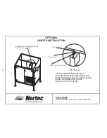
Страница 37: ...N BEAM INSERT RUBBER GASKET PROVIDED ONTO MOUNTING STUD THEN INSTALL THE HEATER THROUGH THE HOLE IN THE HANDLE PLACE THE WASHER AND SECURE INSTALLATION WITH THE NUT MOUNTING STUD HEATER MOUNTING HOLE RUBBER GASKET DETAIL A GH ECLOSURE Heater Installation instructions DWG 1502303 A ...

Страница 38: ...28a 29 33 34 1 2 3 4 5 6 7 11 12 13 14 16 17 26 22 21 25 24 23 30 31 32 15 18 20 28b 8a 9a 9b 10a 8b 9d 10b 35 27 27a 27b 24a 30a 19 9c REPLACEMENT PARTS GH SERIES 34 ...

Страница 39: ...l models 21 Igniter Hot Surface Shielded with gasket all models 22 Sensor Flame Proving with gasket all models 23 Gasket Burner plate all models not shown Flame Sensor Ignitor Kit all models 24 Burner Assembly all models 24a Burner Assembly complete all models 25 Gasket Igniter Shielded all models 26 Sight Window Replacement Kit all models 27 Gas Valve Venturi 36kW all models 27a Elbow Assembly Ai...

Страница 40: ...REPLACEMENT PARTS GH Series 1 2 3 4 5 4 6 4 7 4 8 4 9 10 11 12 13 14 15 16 17 18 22 20 23 24 30 27 28 31 32 3 19 21 26 25 34 33 29 22a 22b 36 ...

Страница 41: ...7203 20 Hex Head Cap Screw all models 21 Terminal Strip all models 22 Transformer 120 24 75VA all models 22a GH Cooling fan assembly without rectifier bridge all models 22b GH Rectifier bridge harness all models 23 Ground CLamp all models 24 Terminal Block 2 Pole all models 25 Power Supply 24VDC all models 26 Electrical Component panel all models 27 Potentiometer 10 0 K ohm for Output GHB 28 Poten...

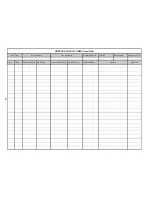
Страница 42: ... Location Responsible Internal no or Tag Date Time First maintenance Mid Season Annual Maintenance Working Hours Water Hardness Signature Remarks NORTEC GHB GHP GHMC Humidifier Unit Type Serial Number Commissioning 38 ...

Страница 43: ... 39 ...

Страница 44: ...es expressed or implied by law No liability whatsoever shall be attached to THE COMPANY until said products have been paid for in full and then said liability shall be limited to the original purchase price for the product Any further warranty must be in writing signed by an officer of THE COMPANY THE COMPANY s limited warranty on accessories not of NORTEC s manufacture such as controls humidistat...

Страница 45: ...IES INC P O Box 698 826 Proctor Avenue Ogdensburg NY 13669 Website www humidity com NORTEC AIR CONDITIONING INDUSTRIES LTD 2740 Fenton Road Ottawa ON K1T 3T7 E mail nortec humidity com A WMH COMPANY PRINTED IN CANADA ...

Отзывы: