of the location, amount of steam being
introduced into the duct, downstream
obstructions, and surfaces vulnerable to
wetting.
3.
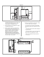
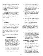
When steam distributors are located in a duct,
they should be in a straight section of duct at
least 6 feet (2 meters) from any elbow or
obstruction. If the duct or plenum conditions
result in poor absorption distance
characteristics, please consult your local
representative or the factory. (See
Engineering Manual, Form # -163D for
information on absorption distances.) See
Figure #9.
4.
Steam distributors should always span the full
width of the air stream. Multiple steam
distributors, arranged in a bank, can minimize
absorption distance.
5.
Exercise extreme caution when installing in
fiberglass or internally lined ducts. If
necessary, remove 4-6 feet of the lining where
the steam is being introduced.
6.
High positive or negative static pressure ducts
or plenums have special requirements. High
positive static pressure ducts may require the
unit to be fitted with an extended external
water trap. Consult factory.
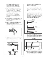
7.
Low temperature ducts below 60°F (15°C),
shallow ducts, or branch ducts might require
the use of a field supplied condensate drain
pan below the steam distributor. See Figure
#10.
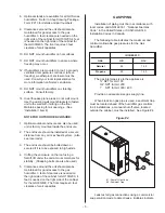
8.
The steam distributor mounting plate is
perpendicular to the steam distributor. When
the mounting plate is attached to the side of
the duct, the distributor is level. An upward or
downward slope to the distributor will result in
poor condensate drainage and “spitting” of
condensate in duct. See Figure #11.
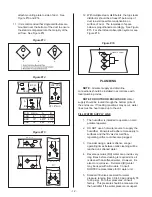
9.
Any distributor longer than 3 feet (1 meter)
should be supported at its end with a threaded
rod through top or bottom of duct. See Figure
#12.
10.
Using duct mounting template provided, cut a
hole in side of duct just large enough to admit
steam manifold and condensate drain pipe
assembly. Use four sheet metal screws to
- 11 -
6 ft
(2m)
Minimum
6ft
(2m)
Minimum
NOTE: Multiple Steam Distributors
Can Reduce the Minimum Distance.
Figure #9
Shallow Duct
Drain Pan
T-Bar Ceiling
To Drain
Branch Duct
Drain Pan
Figure #10
Wrong
Support
(If Needed)
Correct
Always Mount Level
Wrong
Figure #11
Figure #12
Содержание GH 100
Страница 43: ... 39 ...

