Codes, or applicable provisions of the local
building codes.
4.
The required free area of supply air opening
is:
11 in. sq. (7,000 mm
2
), for GH 100
20 in. sq. (13,000 mm
2
), for GH 200
30 in. Sq. (19,500 mm
2
), for GH 300
40 in. Sq. (26,000 mm
2
), for GH 400
NOTE FOR DIRECT VENT OPTION:
The combustion supply air opening is not
required to the room where the appliance is
installed since the combustion air
requirements will be provided through the inlet
air duct (see installation section). To keep
electronic components cooled, it is required to
keep the environment around the unit at room
temperature.
NOTE FOR OUTDOOR ENCLOSURE
:
Required free area of supply air is provided
through the bottom of the unit. Front louvers
ensure good air circulation in the summer.
These louvers should be blocked for winter
operation.
5.
Cabinet back and bottom contain air openings
to provide combustion air to the forced draft
blower. Either the back or bottom set of
openings must have at least 2" (50 mm)
clearance to allow for adequate combustion
air. For example, if the humidifier is floor
mounted, 2" clearance must be maintained to
the unit's back surface.
6.
Excessive exposure to contaminated
combustion air will result in safety and
performance related problems. Known
contaminates include halogens, ammonia, and
chlorides, excessive dust, lime or dirt.
Excessive exposure of electronics to the
contaminants will also result in performance
related problems. Contact NORTEC Technical
Services if you have any questions. If
contaminants exist, it is recommended to use
the outdoor enclosure option to isolate the
unit.
7.
All surfaces are zero clearance to combustible
construction.
NOTES:
The leveling legs must be left in place when
floor mounted on combustible material.
The humidifier shall not be installed directly on
carpeting, tile or other combustible
material other than wood flooring.
8.
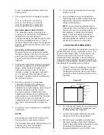
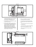
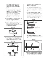
For recommended clearances for servicing
refer to Figure #2.
9.
During installation cover the humidifier to
prevent any dust or other contaminants from
entering the cabinet when activities such as
drilling are taking place.
NOTE:
Some insulating materials may be
combustible. Prior to installing this appliance
examine the area for insulating material. If
this appliance is installed in an insulated
space, it must be kept free and clear of
insulating materials. If insulation is added
after the appliance is installed, it will be
necessary to examine the area again.
LOCATING AND MOUNTING
GH Series humidifiers are designed to mount on a
suitable wall (GH 100 only), GH Stand, or floor. The
clearance dimensions shown in this manual are for
reference only and are the minimum required for
maintenance of the humidifier. Local and National
Codes should be consulted prior to final location and
installation of the humidifier. NORTEC cannot accept
responsibility for installation code violations.
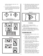
1.
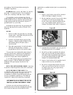
Figure #1 shows the locations of all required
connections to the Gas Humidifier. Careful
consideration should be given to all of these
connections when choosing a location for the
humidifier.
2.
For front and side clearance requirements (for
access during installation, maintenance and
troubleshooting), see Figure #2.
3.
Location of the steam distributor should be
minimum of 36” above the humidifier.
4.
DO NOT locate humidifier any further than
absolutely necessary from steam distributor
location. Net output will be reduced as a result
of heat loss through steam hose (see
Engineering Manual, Form # -163D). Also,
- 3 -
Drain
Gas Input
Line
DWC Water Input
Line*
Power And
Control Wiring
Steam
Outlet(s)
EXHAUST VENT COMES
OUT FROM THE TOP
Fill Water Input
Line
*DWC = Drain Water Cooler
Figure #1
Содержание GH 100
Страница 43: ... 39 ...

