3.
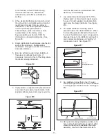
Disconnect wiring connections from
transformer leads labeling as required.
4.
Remove screws (2) holding transformer.
5.
Reverse above procedure to re-install.
Air Switch Replacement
1.
Shut off electrical power to the appliance.
2.
Remove front panel.
3.
Remove wiring connections to switch.
4.
Remove screws (2) holding the switch.
5.
Remove pressure hoses from switch noting
proper location.
6.
Reverse above procedure to re-install.
Drain Pump Replacement
1.
Drain the unit completely. If the pump is
broken see (4.) below.
2.
Shut off electrical power to the appliance.
3.
Remove front and right doors.
4.
If the pump is broken detach hose connecting
the pump with fill cup from fill cup and drain
water manually. Make sure water is cold
enough not to cause injury.
5.
Remove wiring connections to the pump.
6.
Remove hoses attached to the pump.
7.
Remove the pump from the cabinet bracket.
8.
Remove the pump bracket and install it on
new pump.
9.
Reverse above procedure to re-install.
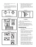
NOTE:
To avoid water spillage (some water
will be left on the tank bottom after manual
draining) use shop vac to remove left over
water.
Combustion Air Blower Replacement
1.
Shut off electrical power and gas supply to the
appliance.
2.
Remove front door and right side panel.
3.
Disconnect electrical plug connection to
blower motor.
4.
Disconnect the pressure hoses at the air
proving switch.
5.
Remove gas train with gas valve / venturi
assembly as described in Gas Valve
Replacement section on page 19.
6.
Remove nuts (4) on discharge outlet of
blower.
7.
Remove blower.
8.
Attach gas valve/ venturi assembly onto new
combustion blower ensuring that the cork
gasket is properly seated and undamaged.
9.
Reverse the above procedure to install new
blower assembly.
10.
Leak test the gas train before
re-commissioning unit.
Tank Replacement
1.
Drain water from unit. See section “Draining
The Tank”.
2.
Switch off power to the unit and open front
and right door.
3.
Disconnect steam and condensate lines.
4.
Remove top cabinet panel with lock key and
lift the door out of the overlapped edge.
5.
Remove tank lid by unscrewing the knobs.
6.
Remove left door/panel.
7.
Disconnect float chamber by releasing the
hose clamps (top and bottom).
8.
Disconnect the blowdown -drain assembly by
releasing the hose clamp.
9.
Remove gas manifold by disconnecting the
coupling bellow the gas valve.
10.
Disconnect high stack unit sensor wires.
Remove exhaust manifold.
11.
Disconnect the wire harnesses from each
burner, ignition module, air proving switch.
12.
12.
Remove nuts holding the heat exchanger. And
pull heat exchanger out. Do not remove the
burners.
- 21 -
Содержание GH 100
Страница 43: ... 39 ...

