-3
2-
5 SQ
6
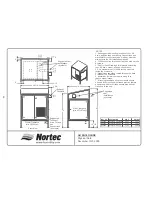
Suggested vent
installations
(by others)
6
12
58 1/2
6 3/4
Front View
Suggested
routing of
drain, fill, and
gas
connections
(by others)
14 1/2
82
72
A
Exhaust
Fan Hood
Suggested
vent
installations
(by others)
GH ENCLOSURE
Physical Data
November 13th, 2000
NOTES:
1. See suggested mounting location of vent, fill,
drain, and gas lines on drawing. Connections and
materials for connections to be made by others at
site (refer to the GH installation manual).
2. 120V connection for exhaust fan to be made at site
by others.
3. See GH Shop Drawings for dimensions locating
vent, fill, drain, steam, and gas connections.
4. As a standard the GH unit is factory mounted
inside the enclosure.
5. Steam lines should be routed through the back
or sides of the enclosure.
6. Insulate and minimze steam run length to
reduce steam losses.
7. If freezing conditions occur, enclosure should
be used in conjunction with freeze proction feature
and back up heater. All lines should also be heat
traced up to the unit.
PART NO.
DESCRIPTION
DIM A
WEIGHT
1502024
Enclosure - GH 300/400
46.25
320 LB
1502025
Enclosure - GH200
27.25
280 LB
1502026
Enclosure - GH100
27.25
280 LB
Frontal Clearance
(min 36”(92cm))
Side Clearance
(min 42”(107cm))
Содержание GH 100
Страница 43: ... 39 ...


