background image

Chapter 10

    Preparation for Using Annotation Function and Measurement Function 

125


Addi

ng Ann

ota

tions 

and Me

asuri

ng


(2) Using 

overlay 

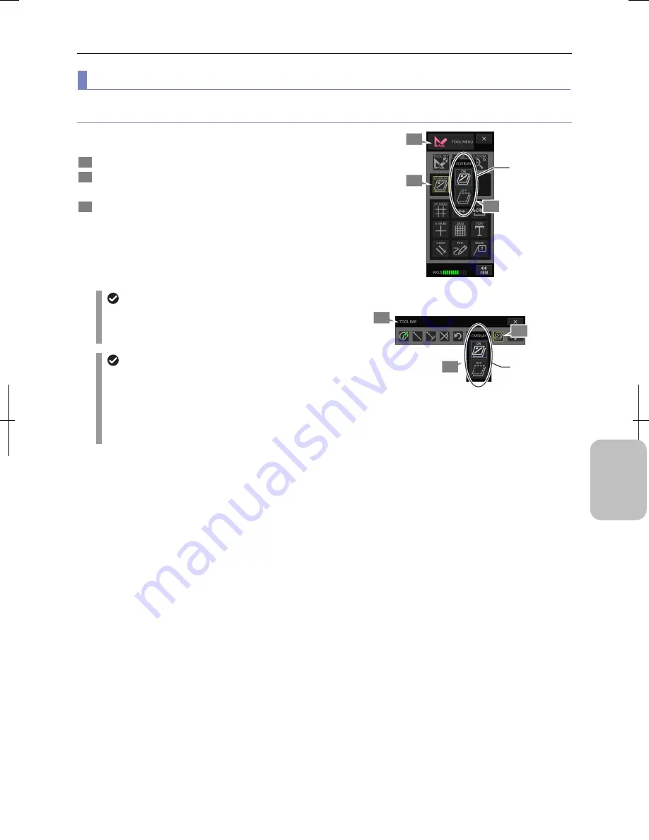
Displaying and hiding an overlay 

You can use the [OVERLAY] button on the [TOOL BAR] of the 
[TOOL MENU] to display or hide an overlay. 

 1 

  Display [TOOL MENU] or [TOOLBAR]. 

 2 

  Press the [OVERLAY] button. 

The [OVERLAY] submenu appears. 

 3 

  Press the [ON] button to display or the [OFF] button to 

hide the overlay. 

 [ON]  Displays overlay. 

 [OFF]  Hides overlay. 

The [OVERLAY] button icon switches in accordance with 
the selection. 


  Automatic display of overlay 

Even when you are hiding an overlay, it automatically 
appears when you press a button on [TOOL MENU] or 
[TOOL BAR] that will draw something on the overlay. 


  Displaying and hiding annotations 

  Since the annotation function (text, straight line, pen, 

and marker) is drawn on an overlay, it is switched 
according to the overlay display/hide setting. 

  The display of each item of scales (XY measurement, 

X scale, scale, cross hairs, and grid line) can be 
independently switched to ON and OFF. 


Switching to Display/Hide the Overlay 

(Using [TOOL MENU]) 


Switching to Display/Hide the Overlay 

(Using [TOOLBAR) 

3

2

Switch to 
display or hide.

1

3

Switch to 
display or hide.

Содержание DS-L3

Страница 1: ...raphing and Playing Images Photographing Basics of DS L3 Please Read First Connecting to PC Printer and Network DS Camera Control Unit DS Camera Head DS Fi2 DS Fi1 DS Vi1 DS Cooled Camera Head DS Qi1Mc DS Fi1c DS Ri1 Instructions Camera Operation M555 E 11 9 NF 1 1 3 M555EN01 ...

Страница 2: ......

Страница 3: ...s notes or information that should be read before use It also marks tips or additional information that may be helpful when using this product Trademarks in this manual Microsoft Windows and Internet Explorer are registered trademarks of Microsoft Corporation in the United States and other countries Macintosh Mac OS and Safari are trademarks or registered trademarks of Apple Inc in the United Stat...

Страница 4: ...can save an image in a specified storage media and a folder Output to an external monitor Images can be output to any commercially available XGA or SXGA external monitor The device supports the DDC Display Data Channel interface enabling itself to automatically identify the video signal of any display that supports the same standard Consecutive capture with interval timer Multiple images can be au...

Страница 5: ...pter 6 Capturing Images with Simple Operations Chapter 7 Tips on Photographing Photographing and Playing Images Chapter 8 Capturing Images with Advanced Setting Menu CAMERA MENU Chapter 9 Playing Back and Deleting Images VIEW MENU Adding Annotations and Measuring Chapter 10 Preparation for Using Annotation Function and Measurement Function Chapter 11 Adding Lines and Annotations to an Image TOOL M...

Страница 6: ...g a DS Camera Head 12 1 Attaching DS camera head to an optical device 12 2 Connecting a DS camera head and DS L3 13 3 2 3 Connecting an External Monitor 14 3 2 4 Connecting USB Peripheral Devices 15 3 2 5 Connecting PC or Printer by USB Cable 16 1 Connecting a PC 16 2 Connecting PictBridge compatible printer 17 3 2 6 Connecting to Network LAN 18 1 Connecting to LAN through a network hub 18 2 Conne...

Страница 7: ...graphing Basics of DS L3 Capturing Images with Simple Operations 42 6 1 Operation of Capturing Images 42 6 2 Displaying CAMERA MENU 43 6 3 White Balance Only for Color DS Camera Heads 44 6 4 Checking Subject Conditions through Live Image 45 6 5 Exposure Compensation 46 6 6 Capturing Displayed Images 47 6 6 1 Capturing a Live Image 48 6 6 2 Capturing after Freezing the Live Image 49 Tips on Photogr...

Страница 8: ...sing DF FL Scene Mode 76 8 3 Configuring Photographing Details 78 8 3 1 Setting Items of the CAM MENU CAMERA Screen 78 1 Switching the image mode operation mode of the image pickup device 79 2 Changing the exposure mode 82 3 Switching the metering mode 84 4 Switching the metering area 85 5 Using the AE lock 88 6 How to use function buttons 89 8 3 2 Setting Items of the CAM MENU IMAGE Screen 90 1 A...

Страница 9: ... 2 4 Registering Calibration Settings 133 11 3 Operating Scales 135 11 3 1 Performing XY Measurement 135 11 3 2 Displaying X Scales Cross Scales 136 11 3 3 Displaying Scales 137 11 3 4 Display Cross Hair and Circles 138 11 3 5 Displaying Grid on Screen 140 11 4 Adding Lines and Comments to an Image 141 11 4 1 Inserting Text Annotation 141 11 4 2 Drawing Straight Lines and Arrows 142 11 4 3 Drawing...

Страница 10: ... cooling camera 173 13 3 Configuring Network Settings 174 13 3 1 Configuring HTTP Server 175 1 Enabling or disabling network connection 175 2 Acquiring an IP address from the DHCP server 176 3 Specifying a fixed IP address and a subnet mask 177 4 Configuring authentication against web browser access 178 13 3 2 Configuring FTP Client 179 1 Enabling or disabling FTP client 179 2 Registering changing...

Страница 11: ...nification When Printed 206 Connecting to Network 207 16 1 Things You can Do with Network 207 16 2 Connecting to Network 208 16 2 1 Items to Check 208 1 Network environment 208 2 PC OS and web browser 209 16 2 2 Configuring Network Settings 210 16 2 3 Connecting to the Network 211 1 Connecting to LAN via a network hub 211 2 Directly connecting to PC without going through LAN 212 16 3 Obtaining Ima...

Страница 12: ...related Operation 254 18 10 Printing 254 18 11 Warning Message List 255 18 12 For Inquiries 257 Capturing from External I O Devices 258 19 1 Functions of the EXT I O Connector 258 19 2 Specifications of External I O Devices 259 Daily Maintenance 260 20 1 Cleaning Utensils and Consumables 260 20 2 Cleaning the DS L3 Main Body 260 20 3 Cleaning the DS Camera Head 260 20 4 Cleaning Optical Devices 26...

Страница 13: ... attempt to disassemble repair or modify this product Doing so may result in electric shock or failure Any failure or damage caused by such action will not be covered under warranty Never attempt to disassemble repair and modify any part of this product which is not described in this manual If you notice any problems with this product contact your nearest Nikon representative Note especially that ...

Страница 14: ... product Do not allow foreign material to enter the inside of this product It may cause malfunction If any foreign material enters inside stop using this product and contact your nearest Nikon representatives 11 Never use this product in a flammable or combustible environment Using it in a combustible gas or dust environment may cause an explosion or fire 12 Do not encumber the heat dissipation of...

Страница 15: ...rature change or left in a high humidity environment for a long time Take special care about the environment when using the product for a long time After a long period of its use leave it idle at least several hours before switching it on again 5 Do not orient the image pickup device to the sun or a high power laser beam Do not orient the photographing section of the DS camera head directly to the...

Страница 16: ... from 20 to 60 C and a relative humidity is 90 or less no condensation Avoid high temperature high humidity locations for installing and storing it Do not place and use this product in a closed space such as a locker or a cabinet Install this product so that there is at least 10 cm of clearance around this product Install this product in a location that is free of dirt and dust Install this produc...

Страница 17: ... should read this part Also refer to this part whenever you want to confirm basic operations during installation and connection of DS L3 or during actual operation of DS L3 This part consists of the following chapters Chapter 1 Before Use Chapter 2 Names of Parts and Their Functions Chapter 3 Installation and Connection Chapter 4 Preparing for Use Chapter 5 Working with Touch Panel ...

Страница 18: ... in the packing box Please make sure that you have everything If any items are missing contact your nearest Nikon representative immediately No Item No Item 1 DS L3 DS Camera Control Unit 5 Stylus with a holder 2 Instruction manual This manual Quick Reference Microscope Operation instruction manual DS L3 6 DS camera cable DS Camera I F cable 20 26 3 0 m 3 AC adapter 7 DS Camera Head with C mount c...

Страница 19: ...pixel White DS Vi1 1 1 8 inch color 2 11 megapixel White DS Qi1Mc 2 3 inch monochrome 1 5 megapixel Equipped Black DS Fi1c 2 3 inch color 5 24 megapixel Equipped Black DS Ri1 2 3 inch color 1 5 megapixel Equipped Equipped Black Note Refer to Chapter 21 Major Specifications for DS camera head specifications Pixel shifting function Pixel shifting is a function that realizes through a PC application ...

Страница 20: ...tal monitor to ensure the high resolution performance Connection cables When you purchase a DVI cable we recommend selecting a cable length of 3 meters or shorter to prevent quality deterioration due to the noise generated from peripheral equipment 2 C mount lens A C mount lens is used when photographing a subject other than those for microscope Any lens that satisfies the following conditions may...

Страница 21: ... printer at the same time Please use a model whose operation is verified by Nikon Not every USB hub is compatible with the DS L3 Note Only one tier of hubs can be connected to DS L3 8 USB cable A USB cable is required for saving image files in a PC and for direct printing on a printer It is recommended to use an AB type cable that is compatible with USB 2 0 USB cables Use a USB cable with ferrite ...

Страница 22: ...ent of the PC depends on the connection method 1 Network connection Machine Windows PC or Mac OS PC OS Windows 7 or Mac OS 10 6 2 USB connection connected as a removable media Machine Windows PC OS Windows 7 3 USB connection When an dedicated application NIS Elements is used The minimum requirements for NIS Elements is as follows different from the recommended environment PC unit Type Windows PC e...

Страница 23: ...le When DS L3 becomes unable to operate normally with some fault this indicator ligts in red Power switch Power switch of DS L3 Pressing the switch turns the power on and pressing it again turns the power off The POWER indicator lights up when the power is on Vent Vent for heat dissipation Vent Vent for heat dissipation Standard stand The stand can be folded When you fix DS L3 to a commercially av...

Страница 24: ...sert a CF card to this slot when you use a CF card for saving images Note Be careful not to insert the card in the opposite direction USB H connectors 2 units Connectors for connecting USB devices such as a USB stick and USB mouse This connector is also used for connecting Nikon microscopes DS L3 has two USB H connectors each of which can have a separate device connected Devices mentioned above ca...

Страница 25: ...use malfunction CAMERA OUT connector Connector for connecting the DS camera head and DS L3 Use the specialized DS camera cable for connecting them C mount General purpose mount for fixing a microscope or optical lens When you photograph with a microscope fix the C mount adapter for connecting the microscope C mount cap Cap for protection from dust To avoid dust adhering on the internal image picku...

Страница 26: ...ne that suits the following conditions DS L3 weight 1 8 kg Mounting screw hole M4 depth 7 mm Screw tightening torque 80 to 120 N cm Described here is a procedure for fixing DS L3 to a commercially available arm Cautions on the built in monitor Be careful not to damage the surface of the built in monitor in this procedure 1 Remove the four screws and the standard stand at the back of DS L3 2 Fix th...

Страница 27: ...or unplugging cables Connecting a cable when the power is on may cause malfunction or failure of the device or electrification 3 2 1 Overall Connection CF CARD Illustration of overall connection DS camera head USB mouse etc To AC socket Network DS L3 External devices PC Printer either one External monitor Nikon microscope AC adaptor Network cable category 5 or 5e USB cable DS Camera cable DVI cabl...

Страница 28: ... mount on the DS camera head Screw it in as far as it will go 4 Insert the C mount adapter to the camera port of the microscope and tighten the clamp screw to fix it Example of microscope mounting Using a relay lens You can also attach a relay lens on the camera port We recommend the x0 7 relay lens for the DS Fi2 DS Fi1 DS Fi1c DS Qi1Mc and DS Ri1 We recommend the x0 55 relay lens for the DS Vi1 ...

Страница 29: ... the original position to lock the connector Connecting a DS camera head and DS L3 Differences between DS camera heads There are six DS camera heads that can be connected to DS L3 Available functions and setting are different depending on the DS camera head model you use Refer to Chapter 17 Differences in Operation Depending on DS Camera Head Models for details Note The model of the connected DS c...

Страница 30: ...r and the other end is a D sub 15 pin connector Connect the DVI I connector of DS L3 and the analog input terminal of the external monitor Note In either case fix the connector by tightening the screw of the cable connector using a screwdriver Connecting an external monitor to DS L3 Operation and setting of an external monitor On off of the signal output to the external monitor is set by SETUP MEN...

Страница 31: ...r one of the two USB H connectors on the DS L3 When two devices are connected simultaneously connect each of them to the USB H connector When three or more devices are connected simultaneously use a USB hub Connecting USB Peripheral Devices Connecting a USB device Only one tier of USB hubs can be connected to this product Do not connect USB devices on the second tire or further because they are no...

Страница 32: ...SB D connector of DS L3 using a USB 2 0 cable AB type Connecting PC with USB cable Setting for PC connection When connecting a PC to DS L3 using a USB cable you need to set the USB interface setting to PTP or vendor default PTP Set it to PTP when you use DS L3 as a removal media device of the PC and set it to vendor when you use NIS Elements This setting is made on the SETUP MAIN screen Refer to 1...

Страница 33: ...irm that the power of DS L3 is off 2 Connect the USB connector of the printer and the USB D connector of DS L3 using a USB 2 0 cable AB type Connecting PictBridge compatible printer by USB cable Setting for printer connection When connecting a printer you need to set the USB interface setting to printer This setting is made on the SETUP MAIN screen Refer to 15 1 1 Setting the USB D Connector Opera...

Страница 34: ...to LAN Use a crossover cable when connecting to PC 1 Connecting to LAN through a network hub Before connecting to the network When you connect DS L3 to a network you need to do the network setting properly according to the network configuration Consult the network administrator of your organization for details Connect DS L3 to your network LAN through a network hub Refer to the figure below for co...

Страница 35: ...the PC and DS L3 directly without a network hub Connecting to the PC directly without using LAN IP address setting When you connect a PC and DS L3 using a crossover cable set fixed IP addresses to PC and DS L3 PC Network cable category 5 or 5e crossover cable DS L3 Left side Connected to Ethernet connector Connected to 10 100M connector LAN connector ...

Страница 36: ...on or fire Refer to Chapter 21 Major Specifications for the power cord specification Because this product falls under the category of electric shock protection class I always make sure to connect it to an AC socket that has a protective ground terminal If you have broken or lost the power cord contact the point where you purchased the product 1 Confirm that the power of DS L3 is off 2 Connect the ...

Страница 37: ...ope on before DS L3 For how to switch on the microscope refer to the manual of your microscope 1 Press the power switch of DS L3 to switch it on Operating power switch When the power is supplied the start screen appears on the monitor and the POWER indicator green starts to blink When DS L3 has been started normally the POWER indicator green stops blinking and becomes on and the image live image c...

Страница 38: ... POWER indicator lights red and an error message shows on the monitor Read the error message and turn the power off After eliminating the cause of the error turn it on again If you cannot remove the error condition contact the point where you purchased the product 4 1 2 Switching Off 1 Press the power switch of DS L3 to switch it off Pressing the power switch when the power is on switches off DS L...

Страница 39: ...button to close the SETUP MENU MAIN screen Setting display language 4 2 2 Setting Date and Time 1 Display the SETUP MENU ADDITIONAL screen Press the SETUP button on the task bar to display the SETUP MENU screen and press the MENU SELECT button and select ADD 2 Set the current date and time in the DATE TIME SET area Enter year month day hour and minutes in two digits For year enter lower two digits...

Страница 40: ...medium Note the following when you use an external recording medium such as a CF card or USB memory stick Carefully read the instructions for the recording medium to be used Insert the recording medium in the correct orientation Do not remove the recording medium or turn off the power while data is being written to it This may cause loss of data or malfunction of the medium Some types of recording...

Страница 41: ...t capturing images See 8 3 4 2 Specifying a save media and folder for details about setting destination for saving images Errors with media A warning message is displayed on the touch panel LCD monitor if an image cannot be saved or played back due to an error If you see a message like this remove the medium once and then connect it again If you see the same message again that recording medium may...

Страница 42: ...bly may damage the CF card or DS L3 Drive number of CF card For a CF card drive number C is always allocated Different media devices are identified by their drive numbers when specifying the storage location and replaying images Drive allocation example Setting the folder for replayed images 2 Removing CF card 1 Confirm that the CF card indicter is off or switch off DS L3 2 Press the eject button ...

Страница 43: ...nector on the right side of DS L3 DS L3 has two USB H connectors both of which can be connected at the same time To connect three USB memory sticks use a commercially available USB hub Note DS L3 recognizes up to three USB memory sticks When you remove a USB memory make sure access to the memory for saving and playing back an image is complete USB memory access lamp is off or switch off the DS L3 ...

Страница 44: ...order of their recognition 3 Press the button for the desired medium any of drive C to F To cancel initialization press the Cancel button at the top without selecting a drive If you select a drive number a media device initialization confirmation message is displayed 4 Press YES to initialize the recording medium or NO to cancel initialization If you select YES the recording medium is initialized ...

Страница 45: ... have bearings on the quality of external monitors Refer to 13 2 2 Configuring Monitor for details Display mode selection SXGA XGA Color balance adjustment of output signal Adjustment of an external monitor using test charts If the screen on the external monitor blurs we suggest that you adjust the clock phase and the clock pitch on the external monitor DS L3 has the capability to output test char...

Страница 46: ...ct such as a ballpoint pen to touch the panel screen Instead of using the stylus you can touch the panel with tip of your finger Be careful not to let your finger nail scratch the screen 5 1 2 Operation Using a Mouse A USB mouse can be used to operate the screen instead of the stylus A pointer is displayed on the screen when a USB mouse is connected Use a mouse to move a cursor and click on the mo...

Страница 47: ...ask bar at the bottom of the screen displays a menu on the screen Operation menu composition and presentation 1 Live image replayed images 2 Task bar 3 CAMERA MENU CAMERA screen Short long IMAGE screen NR SD SET screen SHOT REC screen 4 VIEW MENU PLAY screen THUMBNAIL screen 5 TOOL MENU TOOL screen TOOL SET MAIN screen TOOL SET X HAIRS screen TOOL SET GRID screen TOOL SET CALIBRATION screen 8 SETU...

Страница 48: ... This menu is displayed by selecting PLAY by the MENU SELECT button from the CAMERA MENU An image is displayed by selecting its filename by FILE of VIEW MENU and pressing the PLAY button Pressing the THUMB button switches the screen to the THUMB screen which lists thumbnails of photographed images On this screen you can select desired images play or print them or transfer them by FTP 5 TOOL MENU T...

Страница 49: ... to 60 s DS Fi1 Vi1 1 ms to 60 s DS Fi1c Ri1 Qi1Mc 1ms to 600 s Operation of task bar buttons The task bar has the following buttons to operate CAM button This button displays CAMERA MENU in the upper left section or upper right section of the screen The position of this menu changes between left and right every time the button is pressed TOOL BAR button This button displays TOOL BAR in the upper ...

Страница 50: ...ET MENU INFO MENU and SETUP MENU Pressing this button switches between screens of different menus and windows 1 Switching operation menus 1 Press the MENU SELECT button on a menu screen The MENU submenu is opened 2 Press a desired button The menu switches to the desired menu Switching operation menus CAMERA MENU VIEW MENU 2 1 MENU SELECT button ...

Страница 51: ...and photometry mode You can place three favorite buttons at the button of the screen CAMERA MENU IMAGE screen This menu is for settings of hue and contrast of images The operation items in the upper section of the screen are the same as the CAMERA screen CAMERA MENU NR SD SET screen This menu is for registration of the noise reduction setting shading setting and custom setting as well as for clear...

Страница 52: ...f the unit of measurement reference DS L3 provides two ways of calibration MANUAL in which a subject with a known length is used as the reference and OPTICAL in which the magnification of an optical device is used as the reference 4 Switching between screens of INFO MENU Pressing the INFO button on the task bar displays INFO MENU The following screens can be displayed by pressing the MENU SELECT o...

Страница 53: ...e mode settings and the cooling temperature setting used when a cooled camera is connected SETUP MENU NETWORK screen This screen allows you to make various settings for using DS L3 connected to the network You can make settings of the network basics the HTTP server function and FTP server connection SETUP MENU FILE screen This screen is for settings of the files and folder for saving images You ca...

Страница 54: ...ws you to close the submenu without making any selection You can close the submenu without changing the setting by pressing the Cancel button Selecting an option from submenu Setting a value on the submenu displayed You can set photographing conditions image adjustment and other values using buttons and sliders displayed on the submenu Example EXP CMP button Pressing this button displays a submenu...

Страница 55: ...isplays a submenu that allows you to make operations such as changing magnification moving the display position and canceling enlarged display Some submenus of this type include the x button for closing the submenu In the case of E ZOOM you can close the submenu maintaining the enlarged display Operating from the submenu Operate from the submenu Displays the submenu for the operation Example E ZOO...

Страница 56: ...on microscope is connected to the USB H connector DS L3 controls the motorized equipment of the microscope and displays the detected status of the microscope on the screen Operation method of the microscope control screen For how you operate the microscope control screen refer to a separate volume of this manual Microscope Operation Switching screens When a DS camera head is connected to DS L3 swi...

Страница 57: ...hing Basics of DS L3 Part 2 Photographing Basics of DS L3 This part explains basic operations of DS L3 for photographing capturing images This part consists of the following chapters Chapter 6 Capturing Images with Simple Operations Chapter 7 Tips on Photographing ...

Страница 58: ...image or replayed images and capture them together with the annotations Capturing operation The CAMERA MENU buttons explained in this chapter are also displayed in the Microscope control and Camera microscope screens You can also capture images on the Camera microscope screen with the same operation 6 1 Operation of Capturing Images Images are captured in the following steps 1 Display CAMERA MENU ...

Страница 59: ...sing this button displays submenus allowing you to switch the menu CAPTURE button This button records the image displayed on the screen as a still image E ZOOM button Magnify the image This button enables you to change the magnification and position to display SCENE CSM button This button configures the scene mode and the custom settings X close button Close the menu LEVEL meter This meter is a 12...

Страница 60: ...area Setting white balance Settings at the power on time The setting of white balance is saved when the power is turned off The white balance setting is applied when the power is turned on again If CUSTOM No has been configured in the SETUP MENU MAIN the white balance setting specified by the custom setting is used Using scene mode or custom setting You may want to adjust the contrast or hue in ac...

Страница 61: ...the screen due to the restriction of the optical device or the subject itself you can still enlarge the image using the electronic zoom of DS L3 Press the E ZOOM button of CAMERA MENU to use electronic zoom The E ZOOM submenu is displayed adjust the magnification by the and buttons and move the display position by the up down left and right buttons Pressing the Cancel button resets the magnificati...

Страница 62: ...h the setting Pressing the OK button closes the submenu The value being set is displayed on the EXP CMP button To change the setting start the procedure from pressing the SUB F button again Exposure adjustment Settings at the power on time The setting of exposure compensation is saved when the power is turned off The saved exposure compensation value is applied when the power is turned on again If...

Страница 63: ...When you specify storage media for saving images you need to specify a drive for storage media and a folder Refer to 8 3 4 Setting Items of the CAM MENU SHOT REC Screen for the setting Setting of the recording mode live image or full image file type and image size This setting specifies details of stored images Refer to 8 3 4 Setting Items of the CAM MENU SHOT REC Screen to specify the setting pro...

Страница 64: ...the object is displayed at the proper brightness and with focus on the desired part Checking the live image 2 Press the CAPTURE button of CAM MENU The image file is stored in the specified location You hear a capture sound when you do capturing While the image is being saved the pointer shape changes and the Saved 1 1 message appears on the task bar Upon completion of saving the operable state ret...

Страница 65: ...played are grayed out 3 Check the still image state Check that the still image is displayed as desired To obtain the still image again press the FREEZE button to release freezing and press it again while checking the live image 4 To save the image press the CAPTURE button A capture sound is emitted and the still image is captured and saved in the specified save folder While the image is being save...

Страница 66: ... of the image is saturated white out When the distribution reaches the left end of the histogram the dark part of the image is collapsed black out It is preferred that no white out and black out occurs in the entire image but in some cases adjustment is necessary If a bright part of the image is important adjust the distribution to the left If a dark part is important adjust the distribution to th...

Страница 67: ...on optical path For monochrome images Insert a filter that suits the photographing purpose in the illumination optical path Generally a GIF Green Interference filter achieves a good contrast Using a filter of the complementary color of the specimen makes the contrast sharp Using a filter The way a filter is inserted and removed depends on the microscope Refer to the manual of your microscope A thi...

Страница 68: ...emoving the eyepiece and looking into the eyepiece tube Adjustment of aperture diaphragm For details of the aperture diaphragm adjustment refer to the manual of your microscope For photographed images that have greater depth of focus close down the aperture diaphragm Note that closing down the aperture may limit the performance of the objective What is depth of focus Depth of focus refers to the i...

Страница 69: ...hen using episcopic illumination for microphotography or using a lens adjust the white balance using a white subject For fluorescent photographing we recommend that the white balance be adjusted under normal light conditions before photographing If the screen is excessively dark or bright adjust the luminous energy of the light source or the iris diaphragm or use an ND filter to obtain the appropr...

Страница 70: ...24 8 26 6 6 10 57 Use the following formula for calculating the magnification of the subject on the monitor Magnification on the monitor Optical magnification objective lens magnification X relay lens magnification X Diagonal size of monitor display Diagonal size of effective area for image pickup device Calculation example built in monitor 8 4 inch diagonal 213 mm DS camera head Magnification of ...

Страница 71: ...ages This part explains how to configure various settings to observe and capture images with desired conditions how to display the captured images on the monitor and how to delete them This part consists of the following chapters Chapter 8 Capturing Images with Advanced Setting Menu Chapter 9 Playing Back and Deleting Images ...

Страница 72: ... Note The position of the menu changes to left or right every time the CAM button on the task bar is pressed 2 Press the button in the bottom right corner to change the CAM MENU CAMERA screen to the long screen detailed screen Press the button in the bottom right corner of the long screen detailed screen to return to the short screen If a screen other than CAM MENU is displayed If a screen other t...

Страница 73: ...ode of the long screen is MANU manual the EXP CMP button is displayed as the CAM GAIN button CAMERA long screen detailed screen This screen allows you to configure the image mode and photometry settings In addition to the functions of the short screen this screen includes buttons of IMG MODE EXP MODE MTR MODE MTR AREA and AE LOCK You can place three buttons at the bottom of the screen IMAGE screen...

Страница 74: ... LEVEL meter This meter indicates the exposure status WHITE BL button Sets the white balance Switch display button This button switches the CAMERA screen to the short screen This button is shown as the MAIN button in a CAM MENU other than CAM MENU CAMERA as well as in CAM MENU VIEW MENU and TOOL MENU FREEZE button Pressing this button displays the still image at the time of pressing Pressing it ag...

Страница 75: ...s on the right are CSM1 to CSM7 buttons 2 Press the corresponding button to select a scene mode The submenu closes and the selected scene mode is displayed on the SCENE CSM button of CAM MENU To cancel the selection press the CANCEL button of the submenu Note The scene mode displayed on the submenu changes according to the setting of Select scenes of the SETUP MENU MAIN screen Refer to 13 2 1 2 Ch...

Страница 76: ...Description Dark field fluorescent This mode is used when photographing a dark subject The camera gain sensitivity is improved for better operability of positioning and focusing Use the E MODE function button in combination with this mode to capture an image with less noise For details refer to 8 2 5 Photographing Procedure Using DF FL Scene Mode Bright field This mode is used for general stained ...

Страница 77: ...U Note The scene mode displayed on the submenu changes according to the setting of Select scenes of the SETUP MENU MAIN screen Refer to 13 2 1 2 Changing preset of scene mode for how to change the selection of the scene Using custom setting Comments of custom settings You can enter any comment for a custom setting When a custom setting is selected its comment is displayed in the comment area of CA...

Страница 78: ...dition to suit for observation or capturing 2 Display CAM MENU 3 Press the WHITE BL button The white balance is set and the setting completion message is displayed White balance setting completed 4 Remove the white paper placed in step 1 from the photographing scope Setting white balance Settings at the power on time The setting of white balance is saved when the power is turned off The white bala...

Страница 79: ...tom of the screen On the HISTOGRAM menu the system calculates the distribution of brightness of the image and shows it as a histogram The histogram indicates distribution of brightness for each RGB color which allows fine adjustment of the exposure level The horizontal axis indicates brightness dark to light from left to right The vertical axis indicates appearance frequency On the right to the hi...

Страница 80: ...us priority Confirm that either PROG program AE S AE shutter priority or F AE focus priority is shown on the EXP MODE button Note When it is MANU manual the EXP CMP button is displayed as the CAM GAIN button 3 Press the EXP CMP button The EXP COMP submenu appears 4 Operate on the EXP CMP submenu to adjust the exposure value Setting range 2 0 1 3 step Adjust it viewing the exposure on the live imag...

Страница 81: ...cus priority Confirm that either PROG program AE S AE shutter priority or F AE focus priority is shown on the EXP MODE button Note When the exposure mode is MANU manual exposure the AE LOCK button is not shown 3 Press the AE LOCK button at the position for which you want to lock the exposure The current exposure is locked A blue frame is shown around the AE LOCK button and the OFF mark on the icon...

Страница 82: ... The submenu closes and the configured exposure time is shown on the EXP TIME button and the task bar Configuring exposure time shutter priority or manual Confirming the task bar display The setting range of exposure time for different DS camera heads The table below shows the setting ranges of exposure time for different DS camera heads DS Fi2 130 μs 150 μs 200 μs 300 μs 400 μs 600 μs 800 μs 1 ms...

Страница 83: ...osure is shown on the EXP MODE button Note When it is PROG program AE S AE shutter priority or F AE focus priority the CAM GAIN button is shown as the EXP CMP button 3 Press the CAM GAIN button of CAM MENU The CAMERA GAIN submenu appears 4 Use the button and slider of the CAMERA GAIN submenu to adjust the camera gain value The camera gain setting is common among different DS camera heads and is as...

Страница 84: ...age drive and folder When you specify storage media for saving images you need to specify a drive for storage media and a folder Refer to 8 3 4 Setting Items of the CAM MENU SHOT REC Screen for the setting Setting of the recording mode live image or full image file type and image size This setting specifies details of stored images Refer to 8 3 4 Setting Items of the CAM MENU SHOT REC Screen to sp...

Страница 85: ...t is displayed at the proper brightness and with focus on the desired part Checking the live image 2 Press the CAPTURE button on the MAIN menu The image is captured and the image file is saved in the specified destination You hear a capture sound when you do capturing While the image is being saved the pointer shape changes and the Saved 1 1 message appears on the task bar Upon completion of savin...

Страница 86: ...turns and the task bar display changes from FREEZE to CAM Note Buttons that cannot be used when a still image is displayed are grayed out 3 Check the still image state Check that the still image is displayed as desired To obtain the still image again press the FREEZE button to release freezing and press it again while checking the live image 4 To save the image press the CAPTURE button A capture s...

Страница 87: ...hot with the shot count setting of 10 it shows SAVED 5 10 Image capture condition change during consecutive capture You can change the photographing condition by the operation menu on the screen even when consecutive capture is in progress You can change the exposure or focus during consecutive capture to capture the changes of the object s appearance If it is necessary to capture the object under...

Страница 88: ...W MENU to replay the desired image While an image is replayed VEIW is displayed on the task bar and the x button is displayed in the top right corner of the screen Note The INFO button cannot be used 2 Display CAM MENU using the MENU SELECT button The operation menu switches to that of CAM MENU while the image continues to be replayed Note Operations on CAM MENU are restricted during the replay of...

Страница 89: ...on the screen to set the desired display condition 3 Display CAM MENU using the MENU SELECT button The operation menu switches to that of CAM MENU with the two screen mode maintained Note Operations on CAM MENU are restricted during the replay of the image Disabled buttons are grayed out 4 Press the CAPTURE button The content displayed no the monitor is recorded as it is as an image file 5 To canc...

Страница 90: ... can be used only when the image mode is FULL For details refer to the remarks below 3 Add annotations or measure lengths and angles Add annotations using TOOL MENU and perform measurement using TOOL BAR 4 Display CAM MENU 5 Press the CAPTURE button Among scales on the screen annotations and measurement results that are displayed on the monitor those specified in step 1 will be recorded without ch...

Страница 91: ...DDITIONAL screen The storage destination on the PC is specified by NIS Elements operation For the configuration procedure refer to the manual of NIS Elements PC connection and operation Refer to 3 2 5 1 Connecting a PC for how to connect a PC For how to operate NIS Elements refer to the manual of NIS Elements Capturing images from a PC through the network When DS L3 is connected to the network you...

Страница 92: ...ODE button Exposure assist mode button When this button is pressed DS L3 makes the exposure with a lower camera gain and makes the image pause The image is displayed on the screen as a still image Press the CAPTURE button to save the image F MODE button and E MODE button Note These buttons cannot be used unless they are registered as function buttons For how to register function buttons refer to 1...

Страница 93: ... If the exposure result of the E MODE button is not satisfactory close the still image by the FREEZE button adjust the brightness by camera gain and exposure time while checking the live image and then press the E MODE button to do exposure again Note Adjust the exposure or adjust the contrast and hue on the CAM MENU IMAGE screen as necessary 11 To save the image press the CAPTURE button You hear ...

Страница 94: ...Allows you to select from four options program AE shutter priority focus priority and manual p 82 MTR MODE Allows you to select the mode photometry mode for measuring the brightness of the subject from average photometry and peak hold photometry p 84 MTR AREA Allows you to select an area size measurement area for measuring the brightness of the subject You can also set an arbitrary size and positi...

Страница 95: ...he submenu and the text on the IMG MODE button changes in accordance with the selection Note For details of each image mode refer to the table below Image mode setting The size of the image saved The image size of each image mode varies depending on the DS camera head used The size of the image actually saved varies depending on the image size setting and the recording mode setting of the CAM MENU...

Страница 96: ...This mode obtains and displays a lateral belt shape area in the center of the image pickup device Upper 1 4 and lower 1 4 of the screen are blacked out Recording displaying fast partial images C SCAN This mode obtains and displays a lateral belt shape area in the center of the image pickup device Upper 1 4 and lower 1 4 of the screen are blacked out Recording displaying fast partial images Image m...

Страница 97: ...rame ROI Interlace 12 fps 1280 x 960 ROI S Double speed ROI Progressive 23 fps 1280 x 480 Default FAST DS Vi1 Image mode Read mode Scan method Frame rate Recommended pixel count for recording FULL All pixels read Progressive 15 fps 1600 x 1200 2x2 Double integration Progressive 27 fps 800 x 600 FAST Double speed Progressive 29 fps 800 x 560 C SCAN Center scanning Progressive 29 fps 800 x 560 Defau...

Страница 98: ...ereoscopic microscope F AE Focus priority Increases the camera gain to keep the exposure time short for an easier focusing operation during capture of a dark object Bright spots or banding noise may increase with this mode Use the E MODE function button in combination with this mode to facilitate image capture with less noise Press the E MODE button to change to the Exposure assist mode Exposure t...

Страница 99: ...ser s task of focusing Camera gain 4600 max exposure time 150 ms max When the focus assist mode is selected with F MODE button As F MODE button is pressed F AE automatically adjusts the exposure then the exposure mode changes to MANU automatically Using the F MODE is suitable for application where switching of objectives or illumination is less frequent Camera gain 4600 max Exposure time for the F...

Страница 100: ...etry mode setting Photometry mode options Option Description Average Average photometry mode The average exposure in the photometry area is adjusted to a predetermined value Suitable for most cases this mode is used typically in bright field microscopy for a subject with even brightness over the entire surface when viewed on the monitor Peak Peak hold photometry mode The highest peak exposure in t...

Страница 101: ...er specifies the photometry area Refer to Customizing the photometry area for setting details Setting for power on The size and position of the photometry area is saved at the time of power off and recovered at the next power on If CUSTOM No is set to a registered custom option number in the SETUP MENU MAIN the photometry area size specified by the custom setting is used If the metering area is se...

Страница 102: ...ame display Photometry area frame display The photometry area frame becomes off with the following operations Power off The on off of the frame display is not saved The photometry area frame becomes off when the power is turned on Pause The frame display becomes off when the live image pauses Resuming the live image returns the frame display on Setting two screen mode on Switching the screen to th...

Страница 103: ...otometry area outside the screen Moving the photometry area to the center of the screen Pressing the CENTRNG button moves the photometry area to the center of the screen without changing its size 5 When the photometry area setting is completed press the X button to close the CUSTOMIZE menu The CAM MENU CAMERA long screen is displayed again Customizing the NEW AREA of the photometry area automatica...

Страница 104: ...utter priority or focus priority Confirm that either PROG program AE S AE shutter priority or F AE focus priority is shown on the EXP MODE button Note When the exposure mode is MANU manual exposure the AE LOCK button is not shown 3 Press the AE LOCK button at the position for which you want to lock the exposure The exposure is fixed at this time A blue frame is shown around the AE LOCK button and ...

Страница 105: ...harpness CAM MENU NR SD SET NR SD clear setting and custom setting registration CAM MENU SHOT REC Continuous shot mode log saving and recording mode F mode focus assist mode E mode exposure assist mode TOOL MENU XY measurement X scale scale cross hairs grid text straight line pen and marker Function buttons How to register function buttons For how to register functions as function buttons refer to...

Страница 106: ...91 BK LEVEL Adjust the black level brightness of black of the image p 91 CONTRAST Allows you to select the contrast bright dark contrast of the image from seven preset options p 91 SHARPNESS Adjust the highlighting effect on the edge of the image p 91 Y GAIN button Adjusts the brightness of the image as a whole CHROMA button Adjusts the chroma of the image BK LEVEL button Adjusts the black level b...

Страница 107: ... SET in the CAM MENU NR SD SET screen changes the setting value of each item to the initial value Image adjustment operation Adjustment is made by the buttons and slider in the submenu Adjust the image to the desired condition viewing the live image 1 Pressing the or buttons below the slider changes the value with the smallest steps The button makes the value larger and the button makes it smaller...

Страница 108: ...m the 50 to 50 range initial value 0 step 1 jump 5 Note This menu is not displayed when DS Qi1Mc is connected CHROMA submenu Hue Adjusts the hue of the image A value can be selected from the 50 to 50 range initial value 0 step 1 jump 5 Note This menu is not displayed when DS Qi1Mc is connected HUE submenu Black level Adjusts the black level brightness of black of the image Initial value 0 step 1 j...

Страница 109: ...her ordinary subjects STD Standard contrast Use this option for ordinary photographing Recommended for cells tissue and other ordinary subjects STRONG Strong contrast Use this option to have strong contrast in the image Recommended for cells tissue and other ordinary subjects LINEAR Use this option to obtain an output that is straight linear relative to the input Use this option to study the light...

Страница 110: ... register up to seven adjustment values p 97 CSM SET Registers custom settings Allows you to register up to seven photographing conditions and other settings as custom setting p 98 CLR SET Returns the settings of photographing and others to the initial value p 99 NR button Switches on off of NR noise reduction in image processing SD button Switches the SD shading value CLR SET button Returns the s...

Страница 111: ...ed Setting NR noise reduction Effect of noise reduction Setting the noise reduction on reduces noises in the screen showing a clear image However setting noise reduction on creates residual images set it off when you photograph a moving object or need quicker responses for focusing or other occasions Setting for power on The noise reduction setting is saved at the time of power off and recovered a...

Страница 112: ...7 Selecting any of them closes the submenu and the icon of the SD button changes Setting an SD shading value SD shading adjustment value options Option Description OFF Shading is not performed 10 to 50 Sets the shading adjustment value to 10 20 30 40 or 50 respectively User SD1 to SD7 Uses a registered user defined shading adjustment value Up to seven values can be registered Registration of user ...

Страница 113: ...button from among USD1 to USD7 for specifying the registration number Pressing a button shows a blue frame on the button indicating that the OK button can now be pressed Note The step 4 and 5 can be interchanged 6 Press the OK button to register the user defined shading adjustment value The SD SET submenu closes Note When you have registered a user defined shading adjustment value and closed the S...

Страница 114: ... press the OK button The current setting is saved as the selected custom mode and the CSM Setting submenu closes Note When you have registered a custom setting and closed the CSM SET submenu the SCENE CSM button shows that the custom setting is selected Registering custom setting Recall of a custom setting and automatic selection at the time of startup For how to recall a custom setting refer to 8...

Страница 115: ...reen 2 Press the CLR SET button A message displays for confirmation of the setting clear operation 3 To reset the photographing condition settings to the initial values press YES not to reset press NO The photographing condition is reset to the initial values if you press YES White balance setting Executing CLR SET does not clear the current white balance setting Adjust the setting as needed Retur...

Страница 116: ... Large Frame No change Customizing moving photometry area Center AE lock OFF CAM MENU CAMERA FUNC1 to FUNC3 No change in the function assignment Brightness 100 RB adjustment 100 100 Chroma 0 Hue 0 Color effect Color DS Fi2 DS Fi1 DS Fi1c DS Vi1 and DS Ri1 Monochrome DS Qi1Mc Black level 0 Contrast Standard CAM MENU IMAGE Sharpness 2 NR OFF CAM MENU NR SD SET SD OFF CAM MENU SHOT REC Continuous sho...

Страница 117: ...comment for each image p 104 REC MODE This button allows you to select an image source live image or full image and to select the size pixel count of the stored image and the file type of the image p 105 SHOT MODE button This button specifies whether to photograph a single picture or to perform consecutive capture with interval timer by the capture operation DRIVE button This button specifies the ...

Страница 118: ...sh the setting For the setting range refer to the table below Interval default 10 s The specified value is indicated on the INTERVAL button Starting and stopping consecutive capture To start consecutive capture press the CAPTURE button of CAM MENU The CAPTURE button icon changes to show STOP during consecutive capture Pressing the CAPTURE button again at this time stops consecutive capture For det...

Страница 119: ...lder name maximum of 30 characters and press the ENTER button Deleting a folder To delete the folder selected from the folder list press the DEL button A confirmation message appears Press YES or NO 4 After selecting a drive and a folder press the OK button to finish the setting The SAVE FOLDER submenu closes and the save folder is set Selecting a folder for saving images Selecting a new folder na...

Страница 120: ...BS button to move back one character Pressing the X button closes the keypad without changing the texts Note Closing the keypad by pressing the ENTER button displays the entered comment in the LOG INFO input field On off of log saving and entering a comment Log saving options Option Description OFF A log file is not saved at the time of capturing an image ON The photographing record and a comment ...

Страница 121: ...while LIVE IMAGE is selected as image source Selecting the source of the image Select the live image on the monitor or the full image on the image pickup device as the source of the image to be saved 1 Display the CAM MENU SHOT REC screen 2 Press the REC MODE button The REC MODE submenu is displayed 3 Press one of the following buttons to select the image source to be saved For details of the opti...

Страница 122: ...enu is displayed 3 Select the size of the image When FULL IMAGE is selected as the image source three options are shown for the image size When LIVE IMAGE is selected one to three options are shown according to the current image mode Select the desired image size 4 Press the OK button to return to the CAM MENU SHOT REC menu Pressing the X button closes the REC MODE submenu without saving the setti...

Страница 123: ...x 960 640 x 480 4x4 640 x 480 FAST 1280 x 960 640 x 480 ROI L 1280 x 960 640 x 480 ROI S 1280 x 480 640 x 480 2560 x 1920 1280 x 960 640 x 480 DS Vi1 Image mode Recorded image size live image Recorded image size full image FULL 1600 x 1200 800 x 600 400 x 300 2x2 800 x 600 400 x 300 FAST 800 x 560 400 x 280 C SCAN 1600 x 560 800 x 560 1600 x 1200 800 x 600 400 x 300 DS Qi1Mc Recorded image size li...

Страница 124: ... the REC MODE submenu without saving the setting Selecting a file type Recording mode file type selection options Option Description BMP Color DS camera head Images are recorded as uncompressed 24 bit BMP files Monochrome DS camera head Images are recorded as uncompressed 8 bit BMP files TIFF Color DS camera head Images are recorded as uncompressed 24 bit TIFF RGB files Monochrome DS camera head I...

Страница 125: ...NU Items on the VIEW menu The VIEW MENU includes the following display items VIEW MENU Items Playing Back and Deleting Images 9 1 2 MENU SELECT button The name of the current menu is shown Press this button to switch windows from the submenu PLAY button Display the image selected from the FILE list on the monitor E ZOOM button Magnify the image being played back 2WIN button Divide the screen to ri...

Страница 126: ... a drive is selected all the folders in that drive are displayed in the folder list The list corresponds to the folder hierarchy When you select a folder the list of the subfolders included in the folder is displayed Determining selection Press the OK button to determine the drive and folder The submenu closes The selected folder path is shown in the FOLDER area The list of files included in the f...

Страница 127: ... restricted while the image is being played back When you display the CAM MENU while the image is being played back disabled buttons are displayed in gray Capturing a playback image You can capture an image being played back using the image capture operation An annotation can be added and simplified measurement can be applied to the playback image See Chapter 11 Adding Lines and Annotations to an ...

Страница 128: ...window 3 Press the page switching button at the lower left of the window if necessary to change the thumbnail page If the folder contains more than nine images use the page switching buttons to change the thumbnail page 4 Select the thumbnail of an image to be played The selected thumbnail is marked with a yellow frame 5 Press the PLAY button The selected image appears on the touch panel monitor 6...

Страница 129: ...umbnail images are being loaded only DELETE button Deletes the selected image PRINT button Prints the selected image For details about the print function see Chapter 15 Performing Direct Printing FTP button Transfers the selected image to the FTP server For details about the FTP function see Chapter 16 Connecting to Network Buttons in the Thumbnail Window Operating multiple images collectively Mul...

Страница 130: ...en The magnification of the electronic zoom is indicated on the left of the task bar Changing the display magnification Change the display magnification using the and buttons loupe buttons Moving the display position Move the display position using the up down right and left arrow buttons Canceling the enlarged display Press the CANCEL button to return the display magnification to 1x and close the...

Страница 131: ...e and VIEW FREEZE is displayed on the task bar Note When an image is played back in the 2 window display mode the image is played back in the left window Splitting the Display into Two Windows 3 Perform operations such as moving display range to be the desired window display condition In the 2 window display mode only the middle area of each image is displayed on the right and left windows Pointin...

Страница 132: ...perty of the image file to Read Only if a log file or CSV file is saved also change the property of related log files and CSV files 1 Deleting an image from the folder To delete an image from the FILE list in the playback folder separately perform the following procedure 1 Open the VIEW MENU screen Select the desired folder to show the list in the FILE area 2 Select an image to be deleted from the...

Страница 133: ...ail can be selected and deleted at a time Switch thumbnail windows as needed with the page change button at the lower left of each window 4 Press the DELETE button A confirmation for deletion message appears 5 To delete the image press the YES button Pressing the NO button cancels the operation When YES is selected the image is deleted Note The thumbnail window is updated by re opening the thumbna...

Страница 134: ...TE button A confirmation for deletion message appears 5 To delete the folder press the YES button Pressing the NO button cancels the operation When YES is selected the folder is deleted and the folder list is updated 6 Press the X button to close the submenu Deleting a Folder of Images The case where an image cannot be deleted A confirmation message appears in the following cases You cannot delete...

Страница 135: ...nd Measuring This part describes how to perform operations when using the annotation function and the measurement function of the DS L3 This part consists of the following chapters Chapter 10 Preparation for Using Annotation Function and Measurement Function Chapter 11 Adding Lines and Annotations to an Image Chapter 12 On Screen Measurement ...

Страница 136: ... object on a live or playback image in a simple manner Use the TOOL BAR dedicated for this purpose 10 1 1 Notes about Annotation and Simplified Measurement Notes about annotation and simplified measurement Note the following when you use annotation and simplified measurement Calibration Be sure to check the calibration setting before measuring an object using the annotation or simplified measureme...

Страница 137: ... measurement results can be saved when the image is captured Live image mode Addition of annotations and measurement operation for live images are enabled in any of the following image modes FULL 2x2 4x4 FAST When the image mode is set to ROI L S or C SCAN the image mode automatically changes to FULL Playback image You can add annotation and simplified measurement for a captured image The annotati...

Страница 138: ...or reference of length can be selected from six types nm μm mm cm mil or inch 1 Display the TOOL SET MAIN screen Open the Tool menu press the TOOL SET button and press the MAIN button in TOOL SET button 2 Press the UNIT button and select a unit to use from the submenu Unit mm initial setting nm μm mm cm mil inch six types When a unit is selected the submenu closes and the UNIT button icon changes ...

Страница 139: ... MENU Switching Calibration Setting Using TOOLBAR Calibration settings and overlay information If you switch calibration setting the results of annotation and measurement are treated as follows XY measurement cross scale scale and concentric circle are updated in accordance with the calibration value Annotaions remain the same when the unit is changed Measurement results are completely cleared Reg...

Страница 140: ...how the overlay to make all the results appear at once By using an overlay you can add an annotation and perform measurement without modifying an original image Drawing rendered in an overlay can be saved with an image when captured or printed using the direct printing feature Content of overlay Out of functions operated from the TOOL MENU execution results of the annotation function text straight...

Страница 141: ...cordance with the selection Automatic display of overlay Even when you are hiding an overlay it automatically appears when you press a button on TOOL MENU or TOOL BAR that will draw something on the overlay Displaying and hiding annotations Since the annotation function text straight line pen and marker is drawn on an overlay it is switched according to the overlay display hide setting The display...

Страница 142: ...o erase rendered contents for each overlay item text straight line pen and marker press the ERASE button in the menu of each item Clearing All Overlay Contents Using TOOL MENU Clearing All Overlay Contents Using TOOLBAR Automatically clearing displayed overlay contents Displayed overlay contents annotations and measurement results are automatically cleared erased when the following operations are ...

Страница 143: ...nt can be added to an arbitrary location of the screen 11 4 1 p 141 Straight lines A straight line or arrow can be drawn on the screen 11 4 2 p 142 Pen drawing Any line can be drawn on the screen 11 4 3 p 143 Counting with marker A marker with a number can be drawn on an arbitrary location of the screen Points on the screen can be numbered with markers 11 4 4 p 144 Using mouse When stylus operatio...

Страница 144: ... left or vice versa TOOL MENU Displaying the TOOL MENU Items on the TOOL MENU The TOOL MENU includes the following display items TOOL MENU Items 1 2 MENU SELECT button Name of the menu is displayed on this button Press this button to switch windows from the submenu TOOL SET button Configure annotation and measurement When this button is pressed the TOOL SET button appears A menu on the submenu can...

Страница 145: ... on each menu on TOOL SET to switch to another menu 4 Configure settings in each menu If you see the SAVE button press it to save the settings Content of the setting for each screen is described in the following pages 5 Press the TOOL button to return to TOOL MENU Press the X button to close the menu Switching Setup Menu TOOL setup menus TOOL SET MAIN Configures basic settings as well as saving se...

Страница 146: ...e added to an image when shot Select or clear the six checkboxes XY MEAS X SCALE SCALE X HAIRS GRID and OVERLAY These settings are also applied to printing and obtaining a live image on the web screen Note Items for OVERLAY are annotations and measurement results TOOL SET MAIN Screen Adding annotations and measurement results Scales pasted to images and rendered overlay contents annotations and me...

Страница 147: ...ttings have been completed returns the screen from the RADIUS SETTING screen to the TOOL SET X HAIRS screen Confirm that check marks are added to the selected sizes DASHED checkbox Specify whether cross hairs are drawn with solid or dashed lines When you select the checkbox the cross hairs will be drawn in dashed lines Circles are always drawn in solid lines CENTER checkbox paint center Specify wh...

Страница 148: ...ad appears This field appears when INPUT VALUE is selected HEIGHT input field Enter a numerical value for distance between horizontal grid lines Press the input field The keypad appears This field appears when INPUT VALUE is selected Entering values When you select the input field a keypad appears Press the numerical keys to enter a desired value and then press the ENTER button To erase the entere...

Страница 149: ...ion of the objective of the optical equipment in the input field of the OBJECTIVE area 2 If a relay lens is in use enter the magnification of the relay lens in the input field of the RELAY area When no relay lens is used enter 1 00 When OPTICAL is selected with DS L3 and the motorized microscope connected with a USB cable 1 Enter the magnification of the relay lens in the input field of the RELAY ...

Страница 150: ...RASE button MANUAL mode Entering Values for Each Mode 4 Set the unit of the length in the UNIT area Select a unit from nm μm mm and cm radio buttons 5 Enter a comment maximum 11 characters into the input field of the INFO area as required When you press the input field the keypad appears Press keys to enter information and press ENTER to finish input The entered comment is displayed in the informa...

Страница 151: ...color of the lines You can change line color later 4 Move the measurement lines to a desired location 1 Select a point on the measurement line Guiding lines appear at both sides of the line 2 Move the measurement line using the stylus like dragging by mouse on the screen or movement buttons on the XY MEAS menu 5 To return the measurement line to the center of the screen press the CENTRNG button 6 ...

Страница 152: ...en or movement buttons on the X SCALE menu 4 To return the cross scale to the center press the CENTRNG button 5 To display or hide scales use the DISPLAY checkbox on the X SCALE menu 6 To return to the TOOL MENU press the X button on the X SCALE menu X SCALE Menu 0 1mm 0 1mm 0 1mm 0 1mm Operating Cross Scales Cross scale display The cross scale values are coupled with unit and calibration settings...

Страница 153: ...is changed to a value that does not fit the displayable size the length will be shown as 10 times 100 times etc or 1 10 1 100 etc 5 To display or hide the scale use the DISPLAY checkbox on the SCALE menu 6 To return to the TOOL MENU press the X button on the SCALE menu Displaying Scale Scale display The scale values are coupled with unit and calibration settings If you change the settings the valu...

Страница 154: ...change the color later 4 To change the settings of cross hairs and circles open TOOL SET X HAIRS screen and do the following settings See 11 2 2 Configuring Cross Hairs RADIUS SETTING area Specify the size of a concentric circle to be displayed using checkboxes representing the size from 20 to 360 DASHED checkbox Select the line type of cross hairs solid or dashed Circles are always drawn in solid...

Страница 155: ...d Concentric Circles Cross hairs and concentric circle display The display of the concentric circle is coupled with unit and calibration settings If you change the settings the size of the concentric circles changes The cross hair display does not change The line width of the concentric circle and cross hairs can be changed on the TOOL SET MAIN screen The ON OFF setting of the cross hairs concentr...

Страница 156: ...ore you set again If INPUT VALUE is selected Enter the width and height numerically Choose the reference point either from TOPLEFT or CENTER Press the input field the keypad appears Press keys to enter a desired value and press ENTER key to commit entry Note The minimum grid line distance is 20 pixels No grid lines are displayed if you specify a smaller value 5 Use the DISPLAY checkbox on the GRID...

Страница 157: ... the keypad up to 40 characters Press the SHIFT button for switching upper and lower case Use the CLR button to erase what you have entered Press BS to backspace one character Press the ENTER button when the text is entered Press the X button to close the keypad without saving the text 6 Press the ERASE button on the TEXT menu to delete the entered text Pressing the ERASE button deletes all the te...

Страница 158: ... have arrow shape 6 To erase the line you have drawn press the ERASE button on the S LINE menu Pressing the ERASE button deletes all the straight lines you have drawn 7 Repeat steps 3 to 5 if you want to continue drawing another line 8 Press the X button on the S LINE menu to return to the TOOL MENU 9 To display or hide a rendered line switch to display or hide overlay You cannot selectively displ...

Страница 159: ...ERASE button deletes all the lines you have drawn using the PEN tool 6 Repeat steps 3 to 4 if you want to continue drawing another line 7 Press the X button on the PEN menu to return to the TOOL MENU 8 To display or hide a line drawn using the stylus switch to display or hide overlay You cannot selectively display or hide only lines drawn by the stylus Switch to display or hide the entire overlay ...

Страница 160: ...LOR button on the MARK menu If you change color the counter starts from one If you switch to one of previously used colors the counter starts from the next number of the markers of the color 7 To erase markers you have drawn press the ERASE button on the MARK menu The value of the markers is also reset 8 Press the X button on the MARK menu to return to the TOOL MENU 9 To display or hide markers sw...

Страница 161: ... measurement results and erases an arbitrary measurement result 12 3 3 p 154 Clearing all measurement results Clears rendered overlay contents including all measurement results 12 3 4 p 155 Updating display of overlay Updates screen display and displays all measurement results 12 3 5 p 155 Writing measurement results to CSV file Writes measurement results to a CSV file 12 3 6 p 155 Displaying or h...

Страница 162: ... button hides buttons in the lower row Toolbar Image mode when the measurement function is used When the measurement function is used while the image mode is set to ROI L ROI S or C SCAN the image mode automatically changes to FULL Items on the Toolbar Toolbar Items 1 2 SHOW ALL button 2 COLOR button X Close button HIDE LOWER SECTION OF TOOLBAR button SHOW ALL button ANGULAR MEASUREMENT button CIR...

Страница 163: ...A blue frame appears around the button 4 Specify two arbitrary points A and B on the figure and check distance between the two points If you specify the starting and end points a measurement line is drawn between them and the distance between the two points are shown 5 Repeat step 4 if you want to continue measurement 6 To display or hide the measured result switch to display or hide overlay You c...

Страница 164: ...e is shown 6 Repeat step 5 to continue measuring another perpendicular line from the same reference line 7 To display or hide the measured result switch to display or hide overlay You cannot selectively display or hide only the measured result Switch to display or hide the entire overlay 8 To end measurement press the PERPENDICULAR MEASUREMENT button to deselect the tool Measuring Distance from Re...

Страница 165: ...is displayed 6 Repeat steps 4 and 5 to continue measuring another angle 7 To display or hide the measured result switch to display or hide overlay You cannot selectively display or hide only the measured result Switch to display or hide the entire overlay 8 To end measurement press the ANGULAR MEASUREMENT button to deselect the tool Measuring Angle Undoing and redoing measurement You can cancel an...

Страница 166: ...t step 4 to continue measuring another circle 6 To display or hide the measured result switch to display or hide overlay You cannot selectively display or hide only the measured result Switch to display or hide the entire overlay 7 To end measurement press the CIRCULAR MEASUREMENT button to deselect the tool Measuring Diameter and Circumference of Circle Undoing and redoing measurement You can can...

Страница 167: ...ther side area cannot be measured and NG is displayed 6 Repeat steps 3 to 5 to continue measuring another polygon 7 To display or hide the measured result switch to display or hide overlay You cannot selectively display or hide only the measured result Switch to display or hide the entire overlay Measuring Area of Polygon Undoing and redoing measurement You can cancel and redo measurement by press...

Страница 168: ...er of the first circle to that of the second and distance between the two circles is shown 6 Repeat steps 4 and 5 to continue measuring distance of other circles 7 To display or hide the measured result switch to display or hide overlay You cannot selectively display or hide only the measured result Switch to display or hide the entire overlay 8 To end measurement press the DISTANCE BETWEEN 2 CIRC...

Страница 169: ...e line The length of the perpendicular line is shown For the second and subsequent points distance from the previous point pitch distance is shown as well as the distance to the reference line 6 To display or hide the measured result switch to display or hide overlay You cannot selectively display or hide only the measured result Switch to display or hide the entire overlay 7 To end measurement pr...

Страница 170: ...Measurement Result An order number given to each measurement result is shown Press the ERASE MEASUREMENT RESULT button on the toolbar The toolbar display changes and buttons for selecting execution order of measurement results are shown If the execution history contains more than ten results switch the screen with the upper and lower arrow buttons to the right of the numerical buttons A number tha...

Страница 171: ... there may be a case where previous measurement results disappear If this happens press the UPDATE DISPLAY button on the tool bar to update the screen All the measurement results will be displayed again Updating Display of Overlay 12 3 6 Writing Measurement Results to CSV File Press the SAVE MEASUREMENT RESULTS AS CSV button to write measurement results to a CSV format file extension csv The savin...

Страница 172: ...r hide an overlay with either the tool menu or toolbar Displaying or Hiding Overlay 12 3 8 Switching Calibration Settings Select OFF or any one of M1 to M7 for calibration settings to be the reference for length measurement Calibration must have been set in advance For how to set calibration see 11 2 4 Registering Calibration Settings Note All the executed measurement results are cleared if you sw...

Страница 173: ...g Settings 157 Changing Settings Part 5 Changing Settings This part describes how to change the initial settings of the DS L3 using the SETUP MENU This part consists of the following chapter Chapter 13 Changing Settings ...

Страница 174: ...ying Setup Menu Switching the SETUP MENU screens There is the MENU SELECT button on the top left corner of the SETUP MENU screen If you press this button SETUP submenu is displayed You can switch the SETUP MENU screen to any of the following screens 1 Press the MENU SELECT button of the SETUP MENU The MENU submenu opens and four buttons are displayed MAIN NETWORK FILE and ADD 2 Press a desired but...

Страница 175: ...ttings when a DS cooled camera head is used SETUP MENU NETWORK screen Configures several settings for connecting the system to the network including basic settings HTTP server settings and settings for connecting to an FTP server SETUP MENU FILE screen Configures folders and files for saving images including folders on a recording medium and FTP server file names and initialization of medium SETUP...

Страница 176: ...the updated settings before going to another screen of the SETUP MENU If you go to another screen or close the screen without saving the settings the updated settings are lost and the previous settings are restored Saving Settings Resetting settings to initial settings To clear settings of each screen press the DEFAULT button A confirmation message appears To reset the settings to initial settings...

Страница 177: ...wer part of the CAMERA MENU CAMERA long window OTHERS area Sets the operating mode of the USB D connector on the left side panel of the DS L3 If a DS cooled camera head DS Ri1 or DS Qi1Mc is used the COOLING TEMP button is displayed allowing you to set the cooling temperature of the image pickup device DISPLAY SETTING area Configures color adjustment and backlight settings for the internal monitor...

Страница 178: ...lled when the DS L3 is turned on 1 Display the SETUP MENU MAIN screen 2 Press the CUSTOM No button on the MENU SETTING area The CUSTOM No submenu appears 3 Select the custom settings tto be called on startup CUSTOM1 to CUSTOM7 OFF initial setting When a custom number is selected the submenu closes and the selected content is displayed in the CUSTOM No button 4 Press the SAVE button Custom Settings...

Страница 179: ...Enables scene mode suitable for biological microscopes Initial setting OTHERS Enables scene mode suitable for observation of asbestos Selection of scene mode Use the SCENE CUSTOM button in the CAMERA MENU to select a scene mode 3 Configuring the menu location Set the location of CAMERA MENU displayed when the CAM button on the task bar is pressed 1 Display the SETUP MENU MAIN screen 2 Press the PO...

Страница 180: ... appears 3 Select the desired language For details of choice see the table below ENG initial setting 日本語 When one of these has been selected the submenu closes and the selected content is displayed in the LANG 言語 button 4 Press the SAVE button The display language of menu screens changes Switching Language Choice of Language Choice Seting ENG Switches the display language to English Initial settin...

Страница 181: ...ernal LCD Adjust the color balance of video to be displayed on the internal LCD of the DS L3 1 Display the SETUP MENU MAIN screen 2 Press the LCD COLOR ADJUST button in the DISPLAY SETTING INTERNAL LCD area The INTERNAL LCD COLOR ADJUST window appears 3 Adjust each gain for R red G green and B blue by looking at the screen The window shows a slider and adjustment buttons of each gain of R G and B ...

Страница 182: ... internal LCD XGA LCD OFF Outputs XGA 1024 x 768 signal to the external monitor Nothing is displayed on the internal LCD To reset display mode at startup If the DS L3 is turned on without connecting the external monitor with SXGA LCD OFF or XGA LCD OFF internal LCD OFF setting selected nothing is displayed on the internal LCD disabling any operation in some cases In this case perform the following...

Страница 183: ... environment Initial setting 5 4 Mirroring images Configure mirroring and rotation of a live image Use desired settings in accordance with the position of DS camera head or the status and orientation of a specimen 1 Display the SETUP MENU MAIN screen 2 Press the MIRROR button on the DISPLAY SETTING area The MIRROR submenu appears 3 Press one of the following buttons to configure the look of a live...

Страница 184: ...nitor screen The window shows a slider and adjustment buttons of each gain of R G and B in this order from left Setting range 50 to 150 initial setting 100 for each color R G B Perform adjustment using the slider and left and right adjustment buttons 4 Press the OK button The EXTERNAL DISPLAY COLOR ADJUST window closes 5 Press the SAVE button The configured color balance is saved Configuring Color...

Страница 185: ...button The DDC interface setting is saved Configuring DDC Interface DDC I F Checkbox Setting Choice Setting ON Select this checkbox when using an external monitor conforming to the DDC interface Initial setting OFF Clear this checkbox when using an external monitor that does not conform to the DDC interface When the DDC I F checkbox is selected When the DDC I F checkbox is selected the following f...

Страница 186: ...nctions assignable to the selected button are displayed 3 Press the desired buttons to assign functions The selected functions are displayed in the FUNC1 to FUNC3 buttons If you use no function button select OFF Note Assigned buttons are grayed out and can no longer be assigned One function cannot be assigned to two or more buttons 4 Press the SAVE button The function button setting is saved 5 Dis...

Страница 187: ...after the F MODE button is pressed change the EXPOSURE MODE to PROG E MODE button Exposure assist mode button The E MODE button is used to view and shoot an image with a low camera gain and little noise after focusing using the F MODE button or while a live image is being displayed with the manual exposure mode and a high camera gain in dark field observation or fluorescence microscopy using a mic...

Страница 188: ...tting a reboot request message for the DS L3 5 To switch the setting turn off the DS L3 and then turn it on Configuring Operating Mode of the USB D Connector USB Device Setting Choice Setting PTP Select this mode when connecting the DS L3 to a PC to be used as an external recording medium of the PC Initial setting This mode allows you to open files in the CF card or USB memory of DS L3 from an app...

Страница 189: ... selected content is displayed in the COOLING TEMP button 4 Press the SAVE button The cooling temperature setting is saved Configuring Cooling Camera Cooling Temperature Setting Choice Setting 5 C Sets the image pickup device cooling temperature to Ambient temperature 5 C Initial setting Note This choice is available at an ambient humidity of 80 RH or less 10 C Sets the image pickup device cooling...

Страница 190: ... related settings of this system In this case an alert message of REBOOT REQUIRED appears when you save the setting on the SETUP MENU NETWORK screen X Close button Close the Setup Menu screen INTERNAL SERVER area Configures basic network settings and settings for using this system as an HTTP server EXTERNAL SERVER area Configures settings for connecting to an FTP server on the network and performs...

Страница 191: ...re plugging into the network A wrong setting may cause a failure in your network Network connection No network connection is made unless this setting is enabled even if a network cable is connected 1 Display the SETUP MENU NETWORK screen 2 Select the NETWORK checkbox on the INTERNAL SERVER area Select the checkbox if you want to connect to the network Clear it to disconnect from the network Enable...

Страница 192: ...after the IP address is notified from the DHCP server 3 Press the SAVE button The above setting is saved Acquiring an IP address from the DHCP Server DHCP Checkbox Setting Choice Setting Enable Acquires an IP address from the DHCP server on the network Disable Manually enter an IP address and a subnet mask required for network connection Default Changing IP address Turn off and on the DS L3 after ...

Страница 193: ...the input Press the BS button to backspace one character Pressing the X button closes the keypad without changing the value 4 Press the SAVE button The IP address and subnet mask setting is saved Specifying IP Address and Subnet Mask IP Address Subnet Mask Setting Item Setting IP ADDRESS IP address is a number to identify equipment on the network The DS L3 conforms to IPv4 SUBNET MASK Subnet mask ...

Страница 194: ...ser ID and Password User ID Password Setting Item Setting USER ID Enter a user ID used for access from the web browser up to 10 alphanumeric characters If user authentication is not required leave this field blank or set to anonymous PASSWORD Enter a password used for access from the web browser up to 10 alphanumeric characters If user authentication is not required leave this field blank or set t...

Страница 195: ...80 3 Switching FTP server No 1 to No 5 No 1 to No 5 No 1 p 181 4 Connectivity test against FTP server PING TEST button LOGIN TEST button p 182 1 Enabling or disabling FTP client Disables or enables use of FTP client feature 1 Display the SETUP MENU NETWORK screen 2 Select the FTP CLIENT checkbox on the EXTERNAL SERVER area Select the checkbox if you want to connect to an FTP server Clear it if you...

Страница 196: ...s of the gateway in the GATEWAY field as specified by the network administrator When you press an input field a keypad appears Press the desired key to enter a correct number and press the ENTER button Note The gateway setting is common to all servers 7 Press the SAVE button The settings are stored with the server number Configuring FTP Server FTP Server Setting Choice Setting IP ADDRESS Set the I...

Страница 197: ...VER No button The SERVER No submenu appears 3 Press one of the No 1 to No 5 buttons to select the number of FTP server to be used No 1 to No 5 Initial setting No 1 Registered FTP server settings IP address user ID and password are displayed Note The gateway setting is common to all servers 4 Press the SAVE button The selected server number setting is enabled Switching FTP Server FTP Server Switchi...

Страница 198: ...mined time Performing Connectivity Test by PING When no response is returned for PING test There may be no response to PING if security mechanism such as packet filter firewall or security gateway is introduced Restart the DS L3 before disabling server s security mechanism and retrying the test Even though no response is returned to PING if you are sure you can login to the server by using LOGIN T...

Страница 199: ... MEDIA DIR area Specifies whether to automatically create a folder on a targeted recording medium FILE NAME area Selects file name convention and specifies a prefix SAVE button Save settings of the screen MENU SELECT button Screen name is displayed Pressing the button displays a submenu for switching menus DEFAULT button Restores settings of the screen to initial values Path Information area Shows...

Страница 200: ... do not use automatic folder creation an image file is saved directly in the topmost storage folder of the recording medium or in the home folder of the FTP server 1 Configuring automatic folder creation on recording medium Set whether to automatically create a folder in the storage folder of a recording medium when saving images on the recording medium 1 Display the SETUP MENU FILE screen 2 Enabl...

Страница 201: ...ation is not performed 3 Check the current folder settings by looking at Path Information area 4 Press the SAVE button The auto creation setting is saved Configuring Automatic Folder Creation Automatic Folder Creation Setting Choice Setting Enable Creates a folder automatically in the FTP server Initial setting A folder is automatically created in the home folder of the FTP server with a name of F...

Страница 202: ...t attached to the file saved onto a recording medium 4 Check the file name settings in the Path information area 5 Press the SAVE button The file naming convention setting is saved Configuring File Naming Convention File Naming Convention Setting Choice Setting DATE TIME A file is named based on capturing date DD and time HHMMSS Initial setting When the file name is saved in a medium no prefix is ...

Страница 203: ...ses the submenu When one of the drive buttons C to F is pressed a message to confirm recording medium initialization appears 4 Press YES if you want to initialize the medium or NO to cancel the operation If you select YES the specified medium is initialized Initializing Recording Medium Confirming Initialization Recording Media Initialization Choice Setting C Initializes the CF card inserted into ...

Страница 204: ...onfigures settings for a PictBridge compatible printer and performs test print Note This area is displayed when PRN is selected from USB DEV in the SETUP MENU MAIN screen SAVE button Save settings of the screen MENU SELECT button Screen name is displayed Display a submenu for switching menus DEFAULT button Restore settings of the screen to initial values OTHERS area Configures power saving timer m...

Страница 205: ...t correct date and time especially when you use automatic folder and file name generation since date and time are used for that feature 1 Display the SETUP MENU ADDITIONAL screen 2 Set date and time in the DATE TIME SET area When you press each input field a keypad appears Press the desired key to enter a correct value Press ENTER to commit the value Enter a 2 digit value for each item of date and...

Страница 206: ... Saves an image file in a recording medium connected to the DS L3 Initial setting SAVE TO SERVER Saves an image file in the specified FTP server SAVE TO PC Saves an image file in an arbitrary folder in a PC connected to the DS L3 When SAVE TO PC is selected other items are grayed out and can no longer be selected Note This item is selectable only when USB DEVICE of the DS L3 is set to VNDR The sav...

Страница 207: ... MENU or TOOL MENU Electronic zoom Electronic zoom is a function to enlarge a real image using digital processing 1 Display the SETUP MENU ADDITIONAL screen 2 In the E ZOOM STEP area select zooming levels you want to make available by marking the relevant checkboxes 1 4x 2x 2 8x 4x 6x 8x 10x 16x 3 Press the SAVE button Configuring Electronic Zoom Magnification Electronic Zoom Step Setting Item Set...

Страница 208: ... so that the image matches the printer paper size Real 10 mode Prints an image with fixed magnification so that the printed image becomes the specified size To correct magnification use the CMP 50 150 button For how to set magnification see 15 3 3 Setting Compensation Only in Real 10 Mode CMP 50 150 button Used to set a scaling ratio in the Real 10 mode When this button is pressed a keypad appears...

Страница 209: ...he P SAVE TIMER button is pressed a keypad for numerical input appears Enter a correct value and press the ENTER button to determine the setting Setting range 0 to 99 minutes Initial setting 30 minutes Setting zero 0 disables power saving feature In this case the system never enters standby mode however long the system remains not operated 3 Press the SAVE button The power saving timer setting is ...

Страница 210: ... Displaying a test chart Display a test chart for adjusting monitors when external monitors are used 1 Display the SETUP MENU ADDITIONAL screen 2 Press the LCD CHART button in the OTHERS area to display a test chart A 1 dot pitch black and white mesh chart appears Adjust the clock phase and clock pitch on the display For adjustment method see the instruction guide for the display The automatic adj...

Страница 211: ... Connecting to PC Printer and Network This part describes names of major components of the DS L3 and the configuration of this system This part consists of the following chapters Chapter 14 Connecting to a PC Chapter 15 Performing Direct Printing Chapter 16 Connecting to Network ...

Страница 212: ... displayed in the USB DEVICE button 4 Press the SAVE button If the setting is modified a message to prompt restart of the DS L3 appears 5 To change the setting turn off and on the DS L3 Setting USB D Connector Operating Mode USB Device Setting Choice Setting PTP Select this mode when using the DS L3 as an external recording medium of the PC Initial setting This mode allows you to open files in the...

Страница 213: ...e the DS L3 is turned off 1 Confirm that the DS L3 power is shut off 2 Connect a USB 2 0 cable AB type between the PC s USB connector and the USB D connector of the DS L3 Connecting PC with a USB Cable USB cables Use a USB cable with ferrite core for stabilization of USB transfer reduction of noise generated from the DS L3 and its peripherals and satisfaction of EMC standards PC DS L3 USB 2 0 cabl...

Страница 214: ...sing following the instructions in the dialog box On the PC you can reference recording media of the DS L3 as external recording media Note The AutoPlay dialog box may not be displayed depending on the setting Note The Windows standard device driver is installed as needed at the first connection Example of Display of AutoPlay Dialog Box 4 Perform necessary operations on the PC The following operat...

Страница 215: ...nfigure DS L3 settings and check connection with the PC referring to 14 1 Connecting the DS L3 to a PC Turn off the DS L3 and then connect the USB cable 2 Run the NIS Elements Run the NIS Elements before turning on the DS L3 3 Turn on the DS L3 After the DS L3 has started connection with the DS L3 is recognized by the PC Note The device driver for the DS L3 is installed at the first connection 4 P...

Страница 216: ... set according to equipment to connect and the purpose of use 1 Press SETUP on the task bar to open the SETUP MENU MAIN screen 2 Press the USB DEVICE button in the OTHERS area The USB DEV submenu appears 3 Select PRN The USB DEV submenu has the following choice For details of the setting see the table below PTP initial setting VNDR PRN When one of these has been selected the submenu closes and the...

Страница 217: ...le while the DS L3 is turned off 1 Confirm that the DS L3 power is shut off 2 Connect a USB 2 0 cable AB type between the printer s USB connector and the USB D connector of the DS L3 Connecting PictBridge Compliant Printer with a USB Cable USB cables Use a USB cable with ferrite core for stabilization of USB transfer reduction of noise generated from the DS L3 and its peripherals and satisfaction ...

Страница 218: ...5 2 1 Directly Printing a Live Image by Capturing When you press the CAPTURE button in the operation menu you can print the live image directly in a printer Actions taken in capturing image To print an image in capturing operation set the CAPTURE FUNCTION area in the SETUP MENU ADDITIONAL screen You can save an image in the recording medium or the FTP server and print it out at the same time or on...

Страница 219: ... screen 1 Press the SOURCE button in the VIEW MENU and select a desired folder by switching drives and folders 2 Press the THUMB button in the VIEW MENU The THUMBNAIL screen opens and all image files in the selected folder are displayed 3 Select a desired image and press the PRINT button The selected image is sent to the printer Printing a Saved Image 1 3 Select an image Select a desired folder Pr...

Страница 220: ... be available depending on the printers In this case even though the FRAME checkbox is selected printing is performed without a frame 15 3 2 Selecting Print Mode Real 10 or Normal Mode Select the MAG FIX Real 10 checkbox to switch between the Real 10 and Normal mode The print mode is normal if cleared or Real 10 if selected Normal mode An image is printed in a size that fits the printer paper form...

Страница 221: ...lens magnification X relay lens magnification Example of calculation Reading of scale 500 pixels DS Camera Head Pixel size of Image Pickup Device Optical Equipment Magnification Example Dimension of Scale on Object DS Fi2 DS Fi1 DS Fi1c 3 4 μm Objective lens 40x Relay lens 0 7x 500 pixels x 3 4 μm 40x X 0 7x Approx 61 μm DS Vi1 4 4 μm Objective lens 40x Relay lens 0 55x 500 pixels x 4 4 μm 40x X 0...

Страница 222: ... 4 1600 1200 7 04 5 28 8 8 DS Qi1Mc Ri1 6 45 6 45 1280 1024 8 26 6 6 10 57 Use the following formula for calculating the magnification of the subject on printing paper Magnification on printing paper Optical magnification objective lens magnification x relay lens magnification x Diagonal size of printing paper Diagonal size of effective area for image pickup device Calculation example L size paper...

Страница 223: ...FTP command You can perform operation by sending the FTP command from a PC on a network with the DS L3 working as an FTP server The following operations are available See 16 5 Obtaining Images from the PC Using the FTP Command Sending captured images to the PC Transferring images to the DS L3 Performing advanced control for the DS L3 Operating with the Telnet command You can perform operation by s...

Страница 224: ...management scheme Whether use of a fixed IP address is permitted Whether the DHCP server is running if you plan to obtain IP address automatically Obtaining a fixed IP address Assignment of a fixed IP address to this system is recommended if you plan to use a PC web browser to access this system Consult the network administrator of your organization if you plan to use a fixed IP address You can de...

Страница 225: ...or later Macintosh Mac OS X 10 6 Safari 5 0 or later Firefox 3 6 or later When an FTP server is used In order to transfer images from this system to an FTP server a PC is necessary and FTP server functionality must be configured in it Make sure your server PC has one of the following OS installed Windows Windows 7 Macintosh Mac OS X 10 6 FTP server functionality on Windows You must install the FTP...

Страница 226: ...n the SETUP MENU NETWORK screen 1 Display the SETUP MENU NETWORK screen Press the SETUP MENU button on the status bar Operate MENU SELECT to switch the screen to SETUP MENU NETWORK 2 Follow example below to set each item 3 Press the SAVE button to save settings SETUP MENU NETWORK Screen Display Items Changing network configurations System power may have to be turned off and on to enable changes to...

Страница 227: ...N Use a cross cable to directly connect to a PC 1 Connecting to LAN via a network hub Before connecting to the network Before connecting to the network configure network settings correctly in accordance with the configuration of the network you are going to connect to Consult the network administrator of your organization for details Connect to your network LAN via a network hub Connect the networ...

Страница 228: ...ectly connect a PC and the system without using a network hub Directly Connecting to PC without going through LAN IP address settings Use a fixed IP address for both the PC and this system when connecting them directly using a cross cable PC Network cable Category 5 or 5e cross DS L3 Left side Connect to Ethernet connector Connect to 10 100M connector LAN connector ...

Страница 229: ... on how frequently the images are updated 16 3 1 Configuring PC and Web Browser This section describes the PC and web browser settings for accessing this system The following settings are required 1 Changing firewall settings 2 Changing proxy server settings 3 Enabling Java applets 1 Changing firewall settings In order to protect from unauthorized entry to a PC OS and virus protection software inc...

Страница 230: ...e settings Internet Explorer 1 Start Internet Explorer on your PC 2 Select Internet Options from the Tools menu A dialog box appears 3 Select the Connections tab and click the LAN Settings button The Local Area Network LAN Settings dialog box appears 4 Click the Advanced button If the Advanced button is disabled select the Use a proxy server for your LAN checkbox The Proxy Settings dialog box appe...

Страница 231: ...nd click Settings on the Network tab The Connection Settings dialog box appears 4 Select Manual proxy configuration 5 Write the IP address of this system in the No Proxy for field Enter a dot period per three digit IP address component If the component starts with 0 or 00 skip 0 or 00 and enter the IP address 6 Click OK for every open dialog box to close the dialog boxes The settings are enabled ...

Страница 232: ...web browser You need to connect your PC to the Internet in order to install Java 2 Access the following site with a web browser and download the Java installation file http www java com en download 3 Execute the downloaded file and install Java Follow instructions on the screen to install Java Note 1 If you plan to connect this system and PC with a cross cable or you are going to use this system o...

Страница 233: ...va Applets in Settings to Enable 5 Click OK for every open dialog box The settings are enabled Firefox Windows 1 Start Firefox on your PC 2 Select Options from the Tools menu The Options dialog box appears 3 Open the Content tab in the Options dialog box and select the Enable JavaScript checkbox 4 Click OK to close the dialog box 5 Select Add ons from the Tools menu The Add ons dialog box appears ...

Страница 234: ...references from the Safari menu 3 Select Security Click a top right button if the Security icon is not displayed 4 Select the following checkboxes Enable plug ins Enable Java Enable JavaScript 5 Click the close button to close the dialog box Firefox Macintosh 1 Start Firefox on your PC 2 Select Preferences in the Firefox menu 3 Select Content Click the top right button if the Content icon is not d...

Страница 235: ...ur PC if necessary This operation is available if you are using one of the following combinations of OS and web browsers Download captured images ROOM2 screen Download images stored on a recording medium into your PC Required environment for the ROOM1 screen The ROOM1 screen works in the following environment It may not be displayed properly on other environments OS Web Browser Windows 7 Internet ...

Страница 236: ...nterval and electronic zoom settings displayed on the ROOM1 preview screen may be different from the actual settings used in the screen when more than one PC is accessing the system at the time Settings of the preview screen of the last PC that operated ROOM1 will take effect Note The screen and display examples presented in this document are different depending on the PC OS and web browser being ...

Страница 237: ...M1 check if the personal firewall of your virus protection software is blocking communication with the system Screen switch buttons Tabs Entrance button Return to the Entrance screen Reload button Update the ROOM1 screen ROOM2 button Display the ROOM2 screen Control Pad button Display the Control Pad window You can save the latest live image to a file in BMP TIFF or JPEG format on this window thro...

Страница 238: ...80 0 3 M 1280 x 960 1 2 M DS Vi1 400 x 300 120 K 800 x 600 0 5 M 1600 x 1200 2 M DS Qi1Mc DS Ri1 320 x 256 80 K 640 x 512 0 3 M 1280 x 1024 1 3 M If you make the size larger the display speed of the preview image becomes slower Select an appropriate size for your purpose A certain size cannot be used depending on the system configuration You cannot click that image quality button E Zoom checkbox d...

Страница 239: ...he file name as needed 4 Click the Save button to save the image file The image displayed at the time when this button is clicked is saved BMP and TIFF file names set by initial settings Names of BMP and TIFF files are set as follows in the initial settings DS Camera Head Initial Setting File Name DS Fi2 DS Fi1 DS Fi1c BMP format IMG640 bmp IMG1280 bmp IMG2560 bmp TIFF format IMG640 tif IMG1280 ti...

Страница 240: ...the button is saved Images to be saved A BMP or TIFF image is obtained when the link in the Download BMP or Download TIFF field is clicked Since there is a time lag from the time when a preview image was obtained the preview image may be different from the obtained image The time lag from the preview image increases as the set image size increases A JPEG image is displayed when the link in the Pic...

Страница 241: ...hose listing you want to show CF C button Show listings of a CF card inserted in the CF card slot of the DS L3 USB0 D to USB2 F buttons Show listings of recording media attached to one of USB connectors Listing Up to two levels of folders from to the top of a recording medium and files within the highest folder are displayed Clicking the folder icon or folder name shows folders and BMP JPEG TIFF i...

Страница 242: ... displayed 3 Select a saving location of the image file and change the file name if necessary Even if you click an image file on a listing the image may not be opened If this happens download the image file first then open it To download an image file and save it into your PC open the image file and select Save As operation or right click the image file link and select Save As from the menu Downlo...

Страница 243: ...detailed settings see documents such as online help of the OS or FTP server software Caution In configuring an FTP server on a PC you need to install an FTP server component and add users to the PC In order to accomplish the work you need to log in to a PC as a user having administrative privilege to the PC Ask the PC s administrator for help as necessary 1 Windows 7 Adding the FTP server componen...

Страница 244: ...each 4 Set No SSL for SSL in the Binding and SSL Settings screen and click Next Leave other settings at their default settings 5 Perform the following setting in the Authentication and Authorization Information screen Authentication Set to Basic To enable anonymous login select the Anonymous checkbox Authorization Allow access to Select Specified users and enter the created user name To enable ano...

Страница 245: ... Rule dialog box 6 Open FTP User Isolation select User name directory under Do not isolate users Start users in and then click Apply Close the Internet Information Services IIS Manager 7 Open Computer Management from Administrative Tools in Control Panel and open Computer Management Local System Tools Local Users and Groups Users 8 Double click the user you want to set to open Properties and speci...

Страница 246: ...the same name as the user name will automatically created under Macintosh HD Users If you transfer an image file an FTP folder specified in the DS L3 will be created under the home folder and the image file is stored there Example settings When you set DS1 for the user name and set the DS L3 so that the FTP folder is automatically created the FTP transfer folder is Users DS1 FTyymmdd yymmdd stands...

Страница 247: ...guring Capture Function Overwriting the file with the same name On sending an image to an FTP server no check is done to ensure no file with the same name exists In order to avoid overwriting of an image file configure so that a file name contains date and time information You can use a serial number for file names to avoid this trouble Note that the serial number is reset to 0001 when the name of...

Страница 248: ...pens and all image files in the selected folder are displayed 3 Select the desired image and press the FTP button The selected image is marked with a yellow frame 4 Press the FTP button The selected image is sent to the FTP server Note Multiple images displayed in the thumbnail on the current page can be selected and transferred to an FTP server Transferring Stored Image In case no image is saved ...

Страница 249: ...to make a connection For an example of DS L3 IP address of 192 168 10 2 Example FTP 192 168 10 2 2 Execute the Is command to search the RAMIBOX folder 3 Execute the cd RAMIBOX command The following file names are displayed virtually IMG bmp IMG jpg IMG tif An image size value such as 2560 and 1280 is displayed in the area The file update time at this time is 0 00 but the Get command issuing time i...

Страница 250: ...or of your organization Since unique settings may be made in some organizations executing the Telnet command may cause a network error 1 Open Windows Command Prompt and enter the IP address of DS L3 to make a connection For an example of DS L3 IP address of 192 168 10 2 Example Telnet 192 168 10 2 2 Execute the Telnet command For executable Telnet commands see the Telnet command list Telnet comman...

Страница 251: ...This part provides various information required to operate the DS L3 This part consists of the following chapters Chapter 17 Differences in Operation Depending on DS Camera Head Models Chapter 18 Troubleshooting Chapter 19 Capturing from External I O Devices Chapter 20 Daily Maintenance Chapter 21 Major Specifications ...

Страница 252: ...1c 2 3 inch color 5 24 megapixel Provided Black DS Ri1 2 3 inch color 1 5 megapixel Provided Provided Black Scan method Two scan methods Interlace scan and Progressive scan are available for obtaining images from the image pickup device The Interlace scan can obtain an image by scanning a screen twice Odd scanning lines are scanned first and even scanning lines are scanned next which may cause col...

Страница 253: ...f the image pickup device High definition images can be obtained We also recommend this mode for long time exposure High definition image recording display 2x2 Binning Double integration Interlace 18 fps 1280 x 960 Adds image pickup device s pixel output in units of 2 x 2 horizontal x vertical to obtain an image This mode is effective for capturing dark objects because the sensitivity increases fo...

Страница 254: ...r is recorded as it is in principle Full Image An image is recorded based on the image pickup device output when the image is captured When FAST or ROI image mode is selected image size on the monitor is small However if the recording mode is set to FULL a high definition image can be recorded based on the output of all pixels of the image pickup device when the image is captured Image Size Settin...

Страница 255: ... Read Mode Scan Method Frame Rate Recommended Number of Recording Pixels Setting Use FULL Frame read Interlace 5 9 fps 2560 x 1920 Obtains information of all pixels of the image pickup device High definition images can be obtained We also recommend this mode for long time exposure High definition image recording display 2x2 Binning Double integration Interlace 10 fps 1280 x 960 Adds image pickup d...

Страница 256: ...he monitor is recorded as it is in principle Full Image An image is recorded based on the image pickup device output when the image is captured When FAST or ROI image mode is selected image size on the monitor is small However if the recording mode is set to FULL a high definition image can be recorded based on the output of all pixels of the image pickup device when the image is captured Image Si...

Страница 257: ...e Mode DS Vi1 Image Modes Available for DS Vi1 Image Mode Read Mode Scan Method Frame Rate Recommended Number of Recording Pixels Setting Use FULL Initial setting All pixels read Progressive 15 fps 1600 x 1200 Obtains information of all pixels of the image pickup device High definition images can be obtained We also recommend this mode for long time exposure We recommend this mode normally High de...

Страница 258: ...n principle Full Image An image is recorded based on the image pickup device output when the image is captured When FAST or C SCAN image mode is selected image size on the monitor is small However if the recording mode is set to FULL a high definition image can be recorded based on the output of all pixels of the image pickup device when the image is captured Image Size Setting Image Mode Image Si...

Страница 259: ...Mode Read Mode Scan Method Frame Rate Recommended Number of Recording Pixels Setting Use FULL Initial setting All pixels read Progressive 19 fps 1280 x 1024 Obtains information of all pixels of the image pickup device High definition images can be obtained We also recommend this mode for long time exposure We recommend this mode normally High definition image recording display 2x2 Binning Double i...

Страница 260: ...tored varies depending on image size and file type settings Note For details of setting items see the table below Setting Recording Mode DS Qi1Mc Selection of Image Source Live Image and Full Image Choice Setting Live Image An image is recorded based on the live image on the monitor when the image is captured Image resolution varies depending on the image size setting but the image on the monitor ...

Страница 261: ...t Note the following when you save images in the RAW format If capturing image source is set to LIVE in the REC MENU in the CAM MENU SHOT REC screen an image of the same size as the image mode set at the time is saved Similarly if the image source is set to FULL an image of a size of 1280 x 1024 pixels is always saved In the RAW format only live image is saved during capturing because data from th...

Страница 262: ...pickup device operating mode Image size and live image display speed change according to the selection and the capacity of image file stored when the image is captured changes Note For details of setting items see the table below Selecting Image Mode DS Ri1 Image Modes Available for DS Ri1 Image Mode Read Mode Scan Method Frame Rate Recommended Number of Recording Pixels Setting Use FULL Initial s...

Страница 263: ...image on the monitor is recorded as it is in principle Full Image An image is recorded based on the image pickup device output when the image is captured When ROI image mode is selected image size on the monitor is small However if the recording mode is set to FULL a high definition image can be recorded based on the output of all pixels of the image pickup device when the image is captured Image ...

Страница 264: ...10 C Then press the SAVE button in the SETUP MENU MAIN screen to save the setting Setting Recording Mode DS Ri1 Pixel shift function When DS Ri1 is used the pixel shift function is available using the PC application NIS Elements High definition shooting using the pixel shift function is made available by connecting the DS L3 to a PC with a USB cable and using the NIS Elements For details of this f...

Страница 265: ...ower of the DS L3 The power is turned off The Power Save Timer is working If no button is pressed during a predetermined period this system enters the standby status automatically It returns from the standby when any action is taken Change the auto power save setting on the SETUP MENU ADDITIONAL window The device is hot when touched The system is used in a hot or confined space Use the DS L3 withi...

Страница 266: ...rating the embedded monitor When the stylus cannot be prepared operate the screen by a light touch with your fingertips Do not touch the screen with a sharp or hard object The screen cannot be operated The display of the external monitor cannot be operated When images are output to only the external monitor connect a USB mouse to the DS L3 and then operate the display 18 4 View of Images Symptom P...

Страница 267: ...icroscope dual beam or multiple insert the specified filter For negative positive images generally inserting a green interference filter GIF improves contrast When a complementary color filter of the color of the specimen is inserted contrast becomes strong The contrast of the subject itself is low Consider the illumination or microscopy method The image adjustment is improper Set the CHRM HUE con...

Страница 268: ... an image is temporarily stopped The frequency of updating live images is slow Select the image mode so that the frequency of updating images frame rate becomes high Select the settings of the record mode achieving the desired resolution 18 6 Image Saving Symptom Possible cause Action The recording medium is not inserted correctly Insert the CF card to the card slot or connect the USB memory stick...

Страница 269: ...re no DHCP server is installed To assign IP addresses dynamically using DHCP the DHCP server must be connected to the network The system cannot access the network A PING cannot be passed between the PC and DS L3 The firewall is set Change the setting The proxy setting of the PC has a defect Add the IP address of the DS L3 to the exception setting The DS L3 cannot be accessed from a web browser Alt...

Страница 270: ...he transfer rate is slower than that of USB 2 0 certified products Cannot transmit data normally Two USB hubs are used Keep a USB hub up to one tier When downloading images in a row the same image is downloaded Images are downloaded at intervals shorter than five seconds Images are updated once every five seconds If files are read out at intervals shorter than five seconds the latest image cannot ...

Страница 271: ... not connected Connect the printer NO PRINTER The power of the printer is off Turn on the printer PRINTING FAILED For some reason the print process could not be completed Check whether or not the printer runs out of paper or ink DESTINATIN NOT SPECIFIED The output destination at the time of capture is not specified Or the setting of the output destination is invalid Check the setting of the operat...

Страница 272: ...rformed Check the state of the PC application after confirming that it is now ready to communicate perform the processing again SYSTEM ERROR A critical error occurred inside the system Turn on the system again If this error occurs frequently please contact your supplier INTERNAL ERROR A critical error occurred inside the system Turn on the system again If this error occurs frequently please contac...

Страница 273: ...roduct name Serial No Connected Peripheral Devices CF card USB memory USB mouse microscope or others Manufacturer name Model Manufacturer name Model Manufacturer name Model Your PC for PC related defects Manufacturer name Model Version of OS and SP service pack CPU type and frequency Type and version of your application soft web browser NIS Elements etc Symptom of the problem displayed message inc...

Страница 274: ... C SCAN and capture an image when a capture signal is input The circuit related to capture is represented at the part from 3 pin to GND shown in the circuit diagram on the next page Capture input signal Capturing by switch on close between 3 pin and GND 2 Perform trigger capture when a trigger signal is input from external supported DS camera heads DS Qi1Mc This function operates the DS camera hea...

Страница 275: ... gain Signal timing The following describes the timing sequence of trigger capture Trigger signal Exposure Exposure timing signal Trigger enable signal There is a time lag of up to 0 7 ms from when a trigger signal is input until exposure starts Once a trigger signal is input the next trigger signal is not received until the next capture becomes available Therefore a trigger signal input during th...

Страница 276: ...alcohol ethyl or methyl alcohol and gently wipe away the stains Since absolute alcohol is highly flammable be careful in handling it so that it does not ignite Observe the manufacturer s handling instructions when handling absolute alcohol 20 3 Cleaning the DS Camera Head Wipe off stains on the DS camera head main body with a soft cloth or others in a state where the C mount cap is attached If the...

Страница 277: ...ns Store this system in a location with low humidity where mold is unlikely to form Make sure to attach the C mount cap to store the DS camera head During storage place a plastic cover over the equipment to prevent dust accumulation Before placing the plastic cover turn off the power switch for the DS L3 and wait for the DS L3 to cool down 20 6 Periodic Inspections Charged Periodic inspections are...

Страница 278: ... 3 h 4 h 30 m 6 h Recording media CF card Compact flash card Type I capable USB memory FAT16 FAT32 capable For using a color DS camera head BMP Uncompressed 24 bits TIFF Uncompressed 24 bits JPG FINE Compression ratio approx 1 4 JPG NORMAL Compression ratio approx 1 8 JPG BASIC Compression ratio approx 1 16 File format For using a monochromatic DS camera head BMP Uncompressed 8 bits TIFF Uncompres...

Страница 279: ...Fi1c 1 ms to 1 s For ROI S 1ms to 60 ms For DS Vi1 1 ms to 1 s For C SCAN 1ms to 60ms For DS Ri1 Qi1Mc 1 ms to 1 s Shutter priority Manual 130 μs 150 μs 200 μs 300 μs 400 μs 600 μs 800 μs 1 ms 1 5 ms 2 ms 3 ms 4 ms 6 ms 8 ms 10 ms 15 ms 20 ms 30 ms 40 ms 60 ms 80 ms 100 ms 150 ms 200 ms 300 ms 400 ms 600 ms 800 ms 1 s 1 5 s 2 s 3 s 4 s 6 s 8 s 10 s 15 s 20 s 30 s 40 s 60 s 80 s 100 s 150 s 200 s 3...

Страница 280: ...ra Noise reduction NR Available On Off Setting clear items Temporary stop Clear Live image display Electric zoom 1x when including image mode change Scene Custom OFF Exposure compensation 0 Camera gain Clear exposure mode for PROG Image mode FAST DS Fi2 DS Fi1 DS Fi1c FULL DS Vi1 DS Ri1 DS Qi1Mc Exposure mode PROG Photometry mode Average Photometry area Large Customize Move Center AE lock OFF FUNC...

Страница 281: ...zontal separation TTL VESA standard compliant Screen freeze temporary stop Available Zoom display Electric zoom 1 to 16 times zoom position movable Playback display One exposure display Thumbnail display 9 exposures CF card USB memory playback Dual window display Still image Note1 and live image replayed image and live image still image Note1 and still image Note2 replayed image and live image Not...

Страница 282: ...E802 3 compliant 10Base T 100Base TX DHCP capable HTTP server function web browser display image transfer Telnet server function DS L3 control FTP server function image transfer MIC control FTP client function image transfer Power Input rating 12 VDC 5 2 5 A Power consumption 70 VA for connecting DS camera head DS AC adapter Others Outer dimensions width x height x depth 230 x 200 x 52 mm Weight A...

Страница 283: ...0 x 600 800 x 560 400 x 300 400 x 280 Quantization 14 bit 12 bit Sensitivity Equivalent to ISO 64 Contrast Standard Camera sensitivity For setting x1 Equivalent to ISO 100 Contrast Standard Camera sensitivity For setting x1 Lens mount C mount Protrusion dimensions from the mount surface to the inside of the camera 10 mm or less Image circle ø11 mm C mount Protrusion dimensions from the mount surfa...

Страница 284: ...x 480 640 x 480 1280 x 1024 1280 x 720 640 x 480 Quantization 12 bit Sensitivity Equivalent to ISO 800 Contrast Standard Camera sensitivity For setting x1 Equivalent to ISO 64 Contrast Standard Camera sensitivity For setting x1 Equivalent to ISO 200 Contrast Standard Camera sensitivity For setting x1 Lens mount C mount Protrusion dimensions from the mount surface to the inside of the camera 10 mm ...

Страница 285: ...ved according to EU EN standards 3 conductor type 3 conductor grounding Type H05VV F 1 mm2 3m long maximum rated at 250V AC minimum For using in Japan Detachable cord set with a PSE mark 3 conductor type 3 conductor grounding Type VCTF 3x0 75mm2 3m long maximum rated at 125V AC minimum Outer dimensions length x width x height 120 L x 60 W x 35 H mm Weight 253 g not including the power cord Operati...

Страница 286: ...f this equipment in a residential area is likely to cause harmful interference in which case the user will be required to correct the interference at his own expense This product satisfies the Canada EMI requirements ICES 003 Class A This Class A digital apparatus complies with Canadian ICES 003 Cet appareil numérique de classe A est conforme à la norme NMB 003 du Canada This product satisfies the...

Отзывы: