General Description 2-5
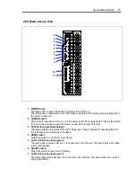
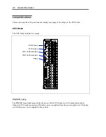
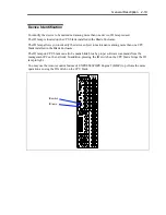
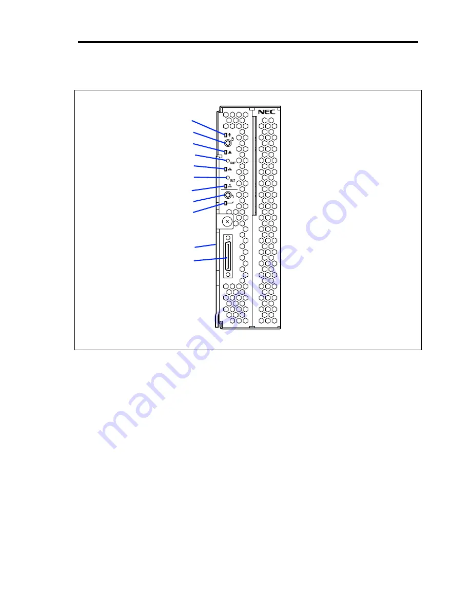
CPU Blade Access Side
1
2
ID
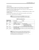
1 POWER lamp
The lamp goes on green when the CPU blade is powered on.
The lamp goes on amber when the CPU blade is powered off but the power is supplied from
the power supply unit.
2 POWER switch
The switch is intended to turn on or off the power of the CPU blade itself. Pressing the switch
for 4 seconds or longer causes the power supply to be turned off forcibly.
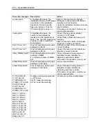
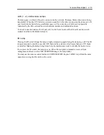
3 STATUS lamp (green/amber/red)
The lamp indicates the status of the CPU blade. See "Lamp Indications" described later for
the indications and meanings of the lamp.
4 DUMP switch
Press this switch to run the memory dump.
5 LAN1 Link/Access lamp (green)
The lamp goes on when LAN port 1 is connected to the network. The lamp blinks when data
is being transmitted.
6 RESET switch
Press this switch to reset the CPU blade.
7 LAN2 Link/Access lamp (green)
The lamp lights when LAN port 2 is connected to the network. The lamp blinks when data is
being transmitted.
1
2
3
4
5
6
7
8
9
10
11
Содержание N8400-086F
Страница 14: ...viii This page is intentionally left blank...
Страница 44: ...2 20 General Description This page is intentionally left blank...
Страница 103: ...Installing the Operating System with Express Setup 5 31 5 Select Perform the Express setup from the Top Menu click Next...
Страница 137: ...Installing and Using Utilities 6 9 4 Click Parameter File Creator Parameter File Creator will appear...
Страница 152: ...6 24 Installing and Using Utilities This page is intentionally left blank...
Страница 158: ...7 6 Maintenance This page is intentionally left blank...
Страница 218: ...A 2 Specifications This page is intentionally left blank...
Страница 290: ...B 72 Installing the Operating System 4 Activate Windows The Windows activation is complete...
Страница 294: ...B 76 Installing the Operating System 3 Process Windows activation according to the following message...


