background image

Welcome.

This
contains information for setting
up and configuring your BladeCenter HT
unit and its components.

For additional information about
your BladeCenter HT device, view
the publications on the

You can

also find the most
current information about
BladeCenter HT devices at
http://www.ibm.com/support/.

Installation and User's Guide

Documentation CD.

Installation and User's
Guide

BladeCenter HT
Type 8740 and 8750

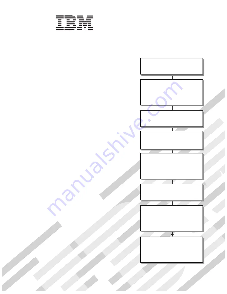
Read the BladeCenter HT overview in

Chapter 1 of this

.

Installation and User's Guide

Define and document the configuration

parameters for your BladeCenter HT unit

using the worksheets in Appendix A of this

.

Installation and User's Guide

Set up your operating environment and

install the rack using the

instructions that come with the rack.

Install the BladeCenter HT unit in the rack

using the instructions in the

or the

BladeCenter

HT 2-Post Rack Installation Instructions

4-Post Rack Installation Instructions.

Install the power modules and

management modules in the BladeCenter HT

unit using the instructions in this

and the documents

that come with each component.

Installation

and User's Guide

Perform initial BladeCenter HT unit

configuration using the instructions in the

Management Module User's Guide.

Install and configure I/O modules in the

BladeCenter HT unit using the instructions in

this

and the documents that come

with each I/O module.

Installation and User's Guide

Install and configure blade servers in the

BladeCenter unit using the instructions in

this

and the documents that come

with each blade server.

Installation and User's Guide

Содержание 87401RU

Страница 1: ...t and install the rack using the instructions that come with the rack Install the BladeCenter HT unit in the rack using the instructions in the or the BladeCenter HT 2 Post Rack Installation Instructi...

Страница 2: ...ify that all optional devices you installed are on the ServerProven list at http www ibm com servers eserver serverproven compat us Is the server working correctly Is the problem solved Hardware or so...

Страница 3: ...BladeCenter HT Type 8740 and 8750 Installation and User s Guide...

Страница 4: ...ting help and technical assistance on page 81 and Appendix C Notices on page 83 Third Edition February 2008 Copyright International Business Machines Corporation 2008 All rights reserved US Government...

Страница 5: ...necting the BladeCenter HT type 8740 to dc power 14 Connecting the BladeCenter HT type 8750 to ac power 16 Disconnecting power from the BladeCenter HT unit 16 BladeCenter HT components and LEDs 18 Fro...

Страница 6: ...alling a CompactFlash module 56 Installing a media tray 57 Installing a power module 58 Installing a blade server 59 Installing the cable management trays without a bezel 60 Installing a dc terminal c...

Страница 7: ...attery return program 86 Electronic emission notices 87 Federal Communications Commission FCC statement 87 Industry Canada Class A emission compliance statement 87 Australia and New Zealand Class A st...

Страница 8: ...vi BladeCenter HT Type 8740 and 8750 Installation and User s Guide...

Страница 9: ...tuotteen lue turvaohjeet kohdasta Safety Information Avant d installer ce produit lisez les consignes de s curit Vor der Installation dieses Produkts die Sicherheitshinweise lesen Prima di installare...

Страница 10: ...ures Read any additional safety information that comes with the server or optional device before you install the device Statement 2 CAUTION When replacing the lithium battery use only IBM Part Number...

Страница 11: ...ts contain an embedded Class 3A or Class 3B laser diode Note the following Laser radiation when open Do not stare into the beam do not view directly with optical instruments and avoid direct exposure...

Страница 12: ...ds ensure that your system electrical requirements do not exceed branch circuit protection requirements Refer to the information that is provided with your device for electrical specifications Stateme...

Страница 13: ...stem earthing electrode conductor is connected v This equipment shall be located in the same immediate area such as adjacent cabinets as any other equipment that has a connection between the earthed c...

Страница 14: ...procedures v Connect and disconnect cables as described in the following table when installing moving or opening covers on this product or attached devices To Connect To Disconnect 1 Turn OFF all powe...

Страница 15: ...does not provide a power control button Removing power supply modules or turning off the server blades does not turn off the electrical current supplied to the device The device also might have more...

Страница 16: ...t normal and single fault conditions do not cause the voltages to exceed a safe level 60 V direct current v Incorporate a readily available approved and rated disconnect device in the field wiring v S...

Страница 17: ...he front of the BladeCenter HT unit and four hot swap fan modules on the rear of the BladeCenter HT unit v Four input output I O module bays that support external network interface connections to netw...

Страница 18: ...rial number _____________________________________________ The serial number machine type and model number are on labels on the top front and rear of the chassis A set of blank labels comes with each B...

Страница 19: ...e business applications and infrastructure quickly to minimize time to market while at the same time ensuring flexibility scalability and availability v Enterprise infrastructure The IBM BladeCenter H...

Страница 20: ...24 29 in With optional bezel 706 mm 27 80 in v Width 442 mm 17 4 in v Weight Full configured weight with blade servers Approximately 158 8 kg 350 lb Empty chassis without modules or blade servers App...

Страница 21: ...nstalled in a bay in the BladeCenter HT unit and shares power fans switches and ports with other blade servers Media tray The BladeCenter HT unit comes with one hot swap media tray in media tray bay 1...

Страница 22: ...ules operates as a redundant pair If either power module fails the remaining power module continues to supply power but there is no redundancy the failed power module must be replaced as soon as possi...

Страница 23: ...iptions of the documents and view documents using Adobe Acrobat Reader or xpdf The Documentation Browser automatically detects the regional settings in use in your system and presents the information...

Страница 24: ...in Portable Document Format PDF on the IBM Documentation CD It contains instructions for installing the BladeCenter HT unit in a 2 post rack v BladeCenter HT 4 Post Rack Installation Instructions Thi...

Страница 25: ...ays and IBM BladeCenter HT Interposer for Gb Switch Bridge Bays with Interswitch Links ISL Installation Instructions This document provides the installation instructions and warranty information for t...

Страница 26: ...portant These notices provide information or advice that might help you avoid inconvenient or problem situations v Attention These notices indicate possible damage to programs devices or data An atten...

Страница 27: ...ule Blade filler Power module filler Management module interposer Management module filler Management module filler tray Media tray Media tray filler Double height filler for the high speed I O module...

Страница 28: ...he type of dc terminal cover you have might vary Both types of dc terminal covers are shown in the following illustration but your BladeCenter HT unit has only one type Chassis Fan module Multiplexer...

Страница 29: ...right connector supplies power to power module 4 Power module 3 IN 3 IN 4 IN 2 IN 1 Power module 1 Power module 2 Power module 4 External A power source right side from rear External B power source l...

Страница 30: ...TN GND 48v RTN GND 48v The BladeCenter HT type 8740 has four dc power terminal connectors Each dc terminal has four M6 0 25 inch studs one for 48 V dc one for RETURN RTN and two for connecting the saf...

Страница 31: ...t draw and the length of wire run or as specified by the customer premises guidelines v Flexible dc wiring is recommended to allow for minimum bend radius v The supply wiring to the power connectors m...

Страница 32: ...Center HT unit by turning off the blade servers and disconnecting the BladeCenter HT unit from the power source To disconnect power from the BladeCenter HT unit complete the following steps 1 Shut dow...

Страница 33: ...l cover on page 42 for more information Nut Flat washer optional Split washer d Remove the nut split washer flat washer and power cord from each terminal post e Remove the power cables v BladeCenter H...

Страница 34: ...controls and LEDs on the front of the BladeCenter HT unit Power module 1 Power module bay 3 Power module 2 Power module bay 4 Media tray 1 Management module 1 Management module bay 2 Media tray bay 2...

Страница 35: ...power LED When this green LED is lit the output from the power module to the other components and blade servers is present and within specifications During typical operation both the input power and...

Страница 36: ...ter HT unit has a major system fault The system can continue to operate but might lose some function and performance Note The color of this LED can be set to amber or red through the advanced manageme...

Страница 37: ...connector 4 Network clock bay 1 Network clock bay 2 Multiplexer expansion module 1 Multiplexer expansion module 2 Fan module 1 Fan module 3 Fan module 2 Fan module 4 Serial connector Alarm panel modu...

Страница 38: ...us with additional functionality for access to a serial port on each blade server in the chassis through an external breakout cable v Power on When this green LED is lit power is present in the BladeC...

Страница 39: ...emove the device from the BladeCenter HT unit v Alarm panel module fault When this amber LED is lit there is a fault on the alarm panel module The system can continue to operate usually without the us...

Страница 40: ...nsion module FRU ready for removal LED Multiplexer expansion module fault LED The multiplexer expansion module controls the USB connectors video signals and management module connections to the blade...

Страница 41: ...age 44 for instructions Note Make sure that the BladeCenter HT unit has adequate power to support all of the installed components The BladeCenter HT unit must contain either two or four power modules...

Страница 42: ...ndicate touch points on hot swap components See the instructions for removing or installing a specific hot swap component for any additional procedures that you might have to perform before you remove...

Страница 43: ...Use an ESD wrist strap whenever you are working on the BladeCenter HT unit and BladeCenter HT components To reduce the possibility of electrostatic discharge observe the following precautions v Use an...

Страница 44: ...ent tray that is installed without the BladeCenter HT bezel complete the following steps Upper cable management tray Lower cable management tray Thumb screws Thumb screws 1 Read the safety information...

Страница 45: ...wer module handle using one of the following procedures v For a power module in one of the upper power module bays push the inner handle release to the right then pull the handle up to the open positi...

Страница 46: ...information that begins on page vii and Installation guidelines on page 26 2 Shut down the blade server operating system then shut down the blade server See the documentation that comes with your blad...

Страница 47: ...ly 0 6 cm 0 25 inch 3 Slide the media tray out of the bay Removing a CompactFlash module To remove a CompactFlash module complete the following steps Primary connector Secondary connector Media tray 1...

Страница 48: ...s from the media tray 4 Press the release button again to eject the CompactFlash module from the media tray Note If the release button for a CompactFlash module is in the out position press the releas...

Страница 49: ...O module 1 Read the safety information that begins on page vii and Installation guidelines on page 26 2 Pull the release handle to the open position The module moves out of the bay approximately 0 6...

Страница 50: ...ation that begins on page vii and Installation guidelines on page 26 2 Remove the I O module or filler from the I O module bay see Removing an I O module on page 33 3 Pull the interposer release handl...

Страница 51: ...igh speed I O module interposer tray To remove an I O module interposer or interposer filler tray complete the following steps High speed interposer tray lower High speed interposer tray upper High sp...

Страница 52: ...ment module 1 Read the safety information that begins on page vii and Installation guidelines on page 26 2 Pull the module release handle to the open position The module moves out of the bay approxima...

Страница 53: ...y information that begins on page vii and Installation guidelines on page 26 2 Remove the management module or filler from the management module bay see Removing a management module on page 36 3 Pull...

Страница 54: ...elease handle open 1 Read the safety information that begins on page vii and Installation guidelines on page 26 2 Pull the release handle to the open position The filler moves out of the bay approxima...

Страница 55: ...ion module Release handle open 1 Read the safety information that begins on page vii and Installation guidelines on page 26 2 Pull the release handle to the open position The module moves out of the b...

Страница 56: ...e Release handle open 1 Read the safety information that begins on page vii and Installation guidelines on page 26 2 Pull the release handle to the open position The module moves out of the bay approx...

Страница 57: ...n module 3 orientation mark Fan module 2 orientation mark Fan module 1 orientation mark Fan module 4 orientation mark Attention While the BladeCenter HT is operating only one fan module should be remo...

Страница 58: ...lock is installed below the release lever that is on the same side as the fan module orientation mark 3 Press down on the release levers on either side of the fan module you are removing The module mo...

Страница 59: ...3 Turn off the power source Note After you disconnect the BladeCenter HT unit from power wait at least 5 seconds before you connect the BladeCenter HT unit to power again 4 If your terminal cover is...

Страница 60: ...iller on page 38 v Multiplexer expansion modules see Removing a multiplexer expansion module on page 39 v Alarm panel module see Removing an alarm panel module on page 40 6 Loosen the four captive thu...

Страница 61: ...uttle into the chassis until it stops 5 Push the release handles to the closed position The shuttle moves back fully into the BladeCenter HT chassis 6 Tighten the four captive thumbscrews on the fan s...

Страница 62: ...se levers 1 Read the safety information that begins on page vii and Installation guidelines on page 26 2 Orient the fan module to the selected fan module bay Fan module fault LED Fan module orientatio...

Страница 63: ...elow the release lever on the same side as the orientation mark on the fan module b Push the shipping block into the slot below the release lever c Install the phillips head screw that attaches the sh...

Страница 64: ...ete the following steps Multiplexer expansion module Release handle open 1 Read the safety information that begins on page vii and Installation guidelines on page 26 2 Make sure that the release handl...

Страница 65: ...andle open 1 Read the safety information that begins on page vii and Installation guidelines on page 26 2 Make sure that the release handle on the module is in the open position 3 Slide the module int...

Страница 66: ...Remove the management module filler and management module tray filler see Removing a management module on page 36 and Removing a management module interposer on page 37 3 Make sure that the release h...

Страница 67: ...ement module interposer if it is not already installed see Installing a management module interposer on page 50 5 Make sure that the release handle on the module is in the open position 6 Slide the mo...

Страница 68: ...that begins on page vii and Installation guidelines on page 26 2 Remove the module filler and filler tray if one is installed see Removing an I O module on page 33 and Removing an I O module interpose...

Страница 69: ...an I O module complete the following steps Handle open I O module 1 Read the safety information that begins on page vii and Installation guidelines on page 26 2 Remove the module filler if one is ins...

Страница 70: ...7 High speed I O bay 8 1 Read the safety information that begins on page vii and Installation guidelines on page 26 2 Remove the high speed module or filler if one is installed see Removing a high spe...

Страница 71: ...all a high speed I O module interposer see Installing a high speed I O module interposer tray on page 54 4 Make sure that the release handles are in the open position 5 Slide the module or filler into...

Страница 72: ...ash module that is already installed remove it see Removing a CompactFlash module on page 31 Raised edge Narrow guide slot Button in position 4 Make sure the CompactFlash release buttons are pushed in...

Страница 73: ...e 26 2 Make sure that the media tray release lever is in the open position and the CompactFlash release buttons are pushed into the in position Media tray CompactFlash release button 3 Slide the media...

Страница 74: ...he module filler if one is installed see Removing a power module on page 29 3 Make sure that the handle on the power module is in the open position 4 Orient the new power module to the selected power...

Страница 75: ...ed in it one or more adjacent bays might be required b When any blade server or device is in any blade bay 7 through 12 power modules must be installed in all four power bays 3 Remove the filler from...

Страница 76: ...fety information that begins on page vii and Installation guidelines on page 26 2 To install the upper cable management tray on the BladeCenter HT complete the following steps a Orient the upper cable...

Страница 77: ...enter HT unit on page 16 for more information 3 Turn off the power source Note After you disconnect the BladeCenter HT unit from power wait at least 5 seconds before you connect the BladeCenter HT uni...

Страница 78: ...dicate that the device is working correctly v Input power and output power LEDs on each power module v OK LED on each management module v OK LED on each I O module 3 Make sure that the power on LED on...

Страница 79: ...odule uses the static IP address Use the management module to configure other BladeCenter HT component settings such as user accounts DHCP or Wake on LAN See the documentation for your management modu...

Страница 80: ...witch traffic on up to two internal switch link interconnections between the peer switches These ports can be configured as a trunk group between these peer switches Note When installing a switch modu...

Страница 81: ...is in PDF at http www ibm com servers eserver xseries systems_management sys_migration ibmdiragent html It is updated every 6 to 8 weeks v Support for IBM and non IBM servers desktop computers workst...

Страница 82: ...66 BladeCenter HT Type 8740 and 8750 Installation and User s Guide...

Страница 83: ...KVM When there is no actively selected video from any blade server the video from blade server 12 is routed to the management module While the management module is restarting there is temporarily no...

Страница 84: ...blade server requests ownership after the operating system has been installed it can take up to 1 minute for the operating system to recognize the devices this is a one time only occurrence Note The o...

Страница 85: ...nd the BladeCenter HT components to identify system errors quickly See Light path diagnostic LEDs on page 74 v Real Time Diagnostics Real Time Diagnostics tests the major components of the BladeCenter...

Страница 86: ...not reveal the cause of problem call for service Important If diagnostic error messages are displayed that are not listed in the Problem Determination and Service Guide make sure that the latest level...

Страница 87: ...s turned on v The KVM is owned by a blade server that supports KVM 2 Reseat the monitor cable 3 Call for service Power problems v Follow the suggested actions in the order in which they are listed in...

Страница 88: ...management module Note Removing the active management module will cause an automatic failover to the redundant management module if one is installed 3 Reset and reconfigure the management module see...

Страница 89: ...connected to a compatible power source and that the power source is working see Supplying power to the BladeCenter HT unit on page 13 2 Reseat the fan module 3 Call for service Media tray problems v F...

Страница 90: ...s Use the following table to find solutions to problems that are identified by LEDs on the front and rear BladeCenter HT system LED panels Lit LED Cause Action BladeCenter HT system LED panels Power o...

Страница 91: ...function and performance 1 Check the error log for messages 2 Look for a lit error LED on the modules and blade servers to locate a failing component v If the error LED is on a module see the document...

Страница 92: ...76 BladeCenter HT Type 8740 and 8750 Installation and User s Guide...

Страница 93: ...ing the BladeCenter HT unit through the management module Information about using the worksheet is provided in the Management Module User s Guide for your management module General settings Management...

Страница 94: ...nfigure only if DHCP is disabled IP address ___ ___ ___ ___ Subnet mask ___ ___ ___ ___ Gateway IP address ___ ___ ___ ___ Internal network interface eth1 Interface IP address ___ ___ ___ ___ Subnet m...

Страница 95: ...mail alerts __ Yes __ No Alerts to be monitored Critical alerts Select all critical alerts Hard disk drive Multiple fan module failures Power failure Temperature VRM failure Multiple switch module fai...

Страница 96: ...address DNS DNS __ Enable __ Disable DNS server IP address 1 ___ ___ ___ ___ DNS server IP address 2 ___ ___ ___ ___ DNS server IP address 3 ___ ___ ___ ___ Security Secure Socket Layer SSL __ Enabled...

Страница 97: ...your IBM product The documentation that comes with BladeCenter HT systems also describes the diagnostic tests that you can perform Most BladeCenter HT systems operating systems and programs come with...

Страница 98: ...800 426 7378 Hardware service and support You can receive hardware service through IBM Services or through your IBM reseller if your reseller is authorized by IBM to provide warranty service See http...

Страница 99: ...TED TO THE IMPLIED WARRANTIES OF NON INFRINGEMENT MERCHANTABILITY OR FITNESS FOR A PARTICULAR PURPOSE Some states do not allow disclaimer of express or implied warranties in certain transactions there...

Страница 100: ...r channel volume KB stands for approximately 1000 bytes MB stands for approximately 1 000 000 bytes and GB stands for approximately 1 000 000 000 bytes When referring to hard disk drive capacity or co...

Страница 101: ...tos de IBM en el sitio web de IBM http www ibm com ibm environment products prp shtml Notice This mark applies only to countries within the European Union EU and Norway This appliance is labeled in ac...

Страница 102: ...formation on disposal of batteries outside the United States go to http www ibm com ibm environment products batteryrecycle shtml or contact your local waste disposal facility In the United States IBM...

Страница 103: ...t cause harmful interference and 2 this device must accept any interference received including interference that may cause undesired operation Industry Canada Class A emission compliance statement Thi...

Страница 104: ...ipment Attention This is a Class A product In a domestic environment this product may cause radio interference in which case the user may be required to take adequate measures Taiwanese Class A warnin...

Страница 105: ...components 18 configuration sheet management module 77 configuring BladeCenter HT unit 63 I O module 63 configuring the management module 63 connectors front 18 serial connector 23 connectors continue...

Страница 106: ...panel 20 front 18 front system panel 19 FRU ready for removal 23 location 22 BladeCenter HT 20 LEDs continued major system fault 20 23 minor system fault 20 23 multiplexer expansion module 24 power mo...

Страница 107: ...lade server 30 cable management tray 28 CompactFlash module 31 dc terminal cover 42 61 fan module 41 fan shuttle 43 high speed I O module 35 high speed I O module interposer 35 I O module 33 I O modul...

Страница 108: ...92 BladeCenter HT Type 8740 and 8750 Installation and User s Guide...

Страница 109: ......

Страница 110: ...Part Number 44R5188 Printed in USA 1P P N 44R5188...

Отзывы: