


7156 Service Guide
Chapter 3: Diagnostics
September 1998
29
Adjust the MICR Check Reader
Paper
Top of Printer
Paper Feed Button
Potentiometers
Led
MICR Read
Head
Carriage
Assembly
Feed Roll
Assembly
The procedures to adjust the MICR check reader involve setting the DIP switches and
adjusting the two MICR check reader potentiometers on the PC board. You will need an
insulated flathead screwdriver with a four-inch long shaft and 1/8 inch flat tip.
Caution:
Do not adjust the potentiometers if the green LED is not lit (indicating the
switches are incorrectly set). Doing so causes an incorrect noise sample.
Note:
You may need to perform the following steps several times to get the
potentiometers adjusted for the least amount of noise.
Note:
The operator panel may differ depending on the model. To put the printer on- or
off-line, use a paper clip or other pointed object to depress the plunger (in place of the On
Line button) on models with that item.
1.
Remove the front cover from the hinge arm assembly.
This will make it easier to perform the adjustment.
a.
Open the hinge arm assembly.
b.
Remove the screws holding the front cover to the hinge arm assembly.
c.
Unsnap the front cover from the hinge arm assembly.
d.
Close the hinge arm assembly to finish the adjustment.
2.
Insert a blank slip into the slip station from the left side so that it covers the MICR read
head, but does not come into contact with the feed rolls.
Be sure that the slip covers the MICR read head and stays in position.
Содержание 7156
Страница 1: ...NCR 7156 Thermal Receipt and Impact Slip Printer Service Guide BD20 1437 A Issue B September 1997...
Страница 16: ......
Страница 20: ...Chapter 1 About the 7156 Printer 7156 Service Guide September 1998 6...
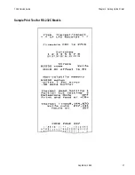
Страница 31: ...7156 Service Guide Chapter 2 Setting Up the Printer September 1998 17 Sample Print Test for RS 232C Models...
Страница 32: ...Chapter 2 Setting Up the Printer 7156 Service Guide September 1998 18 Sample Print Test for LCSIO RS 485 Models...
Страница 34: ...Chapter 2 Setting Up the Printer 7156 Service Guide September 1998 20...
Страница 72: ...Chapter 5 Adjustments 7156 Service Guide September 1998 58...
Страница 79: ...7156 Service Guide Chapter 6 Removing the Thermal Receipt Mechanism September 1998 65...
Страница 81: ...7156 Service Guide Chapter 6 Removing the Thermal Receipt Mechanism September 1998 67...
Страница 99: ...7156 Service Guide Chapter 8 Replacing the Thermal Receipt Mechanism September 1998 85...
Страница 101: ...7156 Service Guide Chapter 8 Replacing the Thermal Receipt Mechanism September 1998 87...
Страница 108: ......
Страница 148: ...Chapter 14 Replacing the Print Mechanism 7156 Service Guide September 1998 134 Enhanced Common PC Board Connectors...
Страница 149: ...7156 Service Guide Chapter 14 Replacing the Print Mechanism September 1998 135 RS 232C PC Board Connectors...
Страница 154: ......
Страница 158: ...Chapter 15 Removing the Base Feed Mechanism 7156 Service Guide September 1998 144...
Страница 164: ...Chapter 16 Forms Compensation Arm Assembly 7156 Service Guide September 1998 150...
Страница 172: ...Chapter 18 Solenoid and Pivot Arm Assemblies 7156 Service Guide September 1998 158...
Страница 178: ......
Страница 198: ...Appendix D Ordering Paper and Supplies 7156 Service Guide September 1998 184...
Страница 204: ...Index 7156 Service Guide September 1998 190...
Страница 205: ......
Страница 206: ...BD20 1437 A Issue B 0998 NCR is the name and mark of NCR Corporation 1997 1998 NCR Corporation Printed in U S A...


