


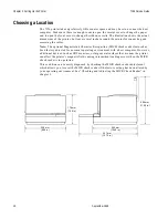


Chapter 2: Setting Up the Printer
7156 Service Guide
September 1998
12
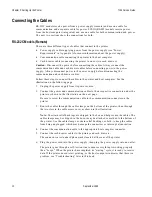
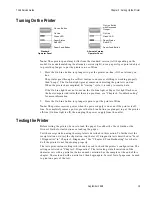
Connecting the Cables
RS-232C models receive power from a power supply (remote) and use one cable for
communication and a separate cable for power. LCSIO (RS-485) models receive power
from the host computer (integrated) and use one cable for both communication and power.
The next two sections show the connections for both.
RS-232C Models (Remote)
There are three different types of cables that connect to the printer:
•
Power supply cable supplying power from the power supply (see “Power
Requirements” in Appendix A for more information about the power supply)
•
Communication cable connecting the printer to the host computer
•
Cash drawer cables connecting the printer to one or two cash drawers
Caution:
Disconnect the power before connecting the cables. Always connect the
communication cable and cash drawer cables before connecting power to the power
supply. Always disconnect power to the power supply before disonnecting the
communication and cash drawer cables.
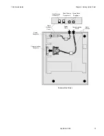
Follow these steps to connect the cables to the printer and host computer. See the
illustration on the following page.
1.
Unplug the power supply from its power source.
2.
Connect the power and communication cables to their respective connectors under the
printer as shown in the illustration on the next page.
Be sure to screw the communication cable to the communication connector on the
printer.
3.
Route the cables through the cable clamps on the bottom of the printer, then through
the two slots in the cable access cover as shown in the illustration.
Note:
The strain relief bushings are shipped in the box and help secure the cables. The
cable clamps may be shipped in the box or may be attached or molded to the bottom of
the printer. Use the cable clamps or strain relief bushings, or both, to keep the cables
from being unplugged which may damage the connectors or interrupt a transaction.
4.
Connect the communication cable to the appropriate host computer connector.
5.
Connect the cash drawer cables to the printer and cash drawers.
The connectors are standard phone jacks located at the rear of the printer.
6.
Plug the power cord into the power supply, then plug the power supply into an outlet.
The printer goes through a self-test routine to ensure everything is working properly
then “beeps.” When the printer has completed its “startup” cycle, it is ready to receive
data. If the printer doesn't start printing, or the host computer indicates that there is a
problem, see “Troubleshooting” later in this book.
Содержание 7156
Страница 1: ...NCR 7156 Thermal Receipt and Impact Slip Printer Service Guide BD20 1437 A Issue B September 1997...
Страница 16: ......
Страница 20: ...Chapter 1 About the 7156 Printer 7156 Service Guide September 1998 6...
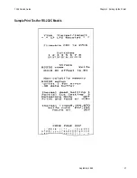
Страница 31: ...7156 Service Guide Chapter 2 Setting Up the Printer September 1998 17 Sample Print Test for RS 232C Models...
Страница 32: ...Chapter 2 Setting Up the Printer 7156 Service Guide September 1998 18 Sample Print Test for LCSIO RS 485 Models...
Страница 34: ...Chapter 2 Setting Up the Printer 7156 Service Guide September 1998 20...
Страница 72: ...Chapter 5 Adjustments 7156 Service Guide September 1998 58...
Страница 79: ...7156 Service Guide Chapter 6 Removing the Thermal Receipt Mechanism September 1998 65...
Страница 81: ...7156 Service Guide Chapter 6 Removing the Thermal Receipt Mechanism September 1998 67...
Страница 99: ...7156 Service Guide Chapter 8 Replacing the Thermal Receipt Mechanism September 1998 85...
Страница 101: ...7156 Service Guide Chapter 8 Replacing the Thermal Receipt Mechanism September 1998 87...
Страница 108: ......
Страница 148: ...Chapter 14 Replacing the Print Mechanism 7156 Service Guide September 1998 134 Enhanced Common PC Board Connectors...
Страница 149: ...7156 Service Guide Chapter 14 Replacing the Print Mechanism September 1998 135 RS 232C PC Board Connectors...
Страница 154: ......
Страница 158: ...Chapter 15 Removing the Base Feed Mechanism 7156 Service Guide September 1998 144...
Страница 164: ...Chapter 16 Forms Compensation Arm Assembly 7156 Service Guide September 1998 150...
Страница 172: ...Chapter 18 Solenoid and Pivot Arm Assemblies 7156 Service Guide September 1998 158...
Страница 178: ......
Страница 198: ...Appendix D Ordering Paper and Supplies 7156 Service Guide September 1998 184...
Страница 204: ...Index 7156 Service Guide September 1998 190...
Страница 205: ......
Страница 206: ...BD20 1437 A Issue B 0998 NCR is the name and mark of NCR Corporation 1997 1998 NCR Corporation Printed in U S A...


