


JuLI™ Stage EDIT Software
78
JuLI
TM
Stage - User Manual
Quick Workflow to export a modified data set
1. Select a well and position
2. Choose either all positions of the data set, the current whole well, or only the
current position will receive modifications
3. Select one or all time-points or a time window
4. Edit the channels
5. Press
Apply
6. Press
New Project
and select a directory, confirm
11.2.3
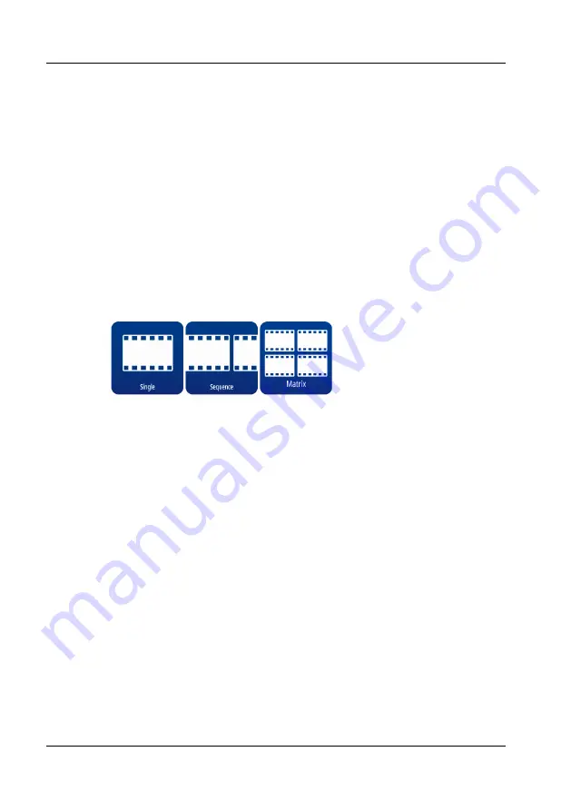
Movie Maker
The movie maker allows to convert time-lapse images into movies using three
different methods:
Single
,
Sequence
, and
Matrix
.