background image

Operation 

JuLI™ Stage - User Manual 

33 

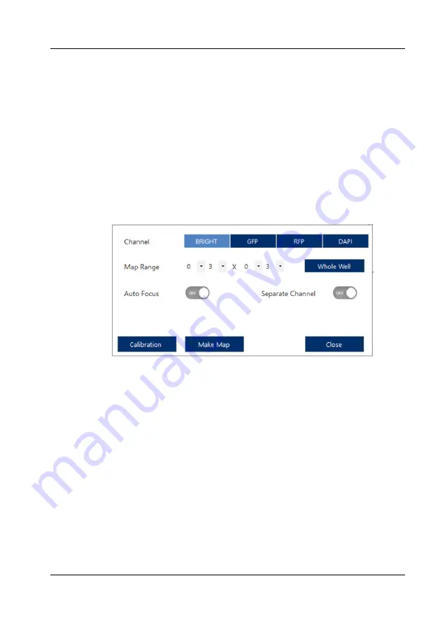
Map mode 

To browse big samples, look for imaging positions, or calibrate the stitching you can 
use the Map Mode. 

Click 

Map Mode 

and then

 Make Map

 to open the menu. 

1.  Select the channel, map range, and check whether or not to use the autofocus 

or  to  separate  the  channels  (if 

Separate  Channel

  is  turned  off,  all  selected 

channels will be overlayed in the map).  

2.  Click 

Make Map

 and browse the enhanced view of your sample in the map view.  

3.  Click 

Cancel

 or 

Apply

 to return to the map mode. 

4.  To toggle the map view click 

Load

 (in 

Preview

 tab only). The navigation zoom 

can be toggled by clicking 

N

 (in 

Preview

 tab only). 

5.  In the 

Setup

 tab you can also add these positions to the position list 


Calibration for map mode (Stitching calibration) 

If there are unwanted overlapping regions in stitched images or during map mode 
you can correct these. 

1.  Click 

Calibration

 in the menu. 

2.  Select 

Horizontal Axis Mode

3.  Click 

Calibration distance

 to adjust the Y-axis overlapping location. Drag the 

images into appropriate positions. 

4.  Click 

Vertical Axis Mode

5.  Click 

Calibration distance

 to adjust the X-axis overlapping location. Drag the 

images into appropriate positions. 

Содержание JuLi Stage

Страница 1: ......

Страница 2: ...eon Hwaseong si Gyeonggi do 18531 Korea Tel 82 2 6220 7940 Fax 82 2 6220 7999 NanoEntek America Inc 220 Bear Hill Road Suite 102 Waltham MA 02451 USA Tel 1 781 472 2558 Fax 1 781 790 5649 The informat...

Страница 3: ...rating environment 17 4 4 Cautions 17 5 User interface 20 6 Basic operation 22 6 1 Moving 22 6 2 Selection 24 6 3 Position zoom 26 6 4 Mouse wheel 27 7 Operation 29 7 1 Preview menu 29 7 2 Setup menu...

Страница 4: ...ence 84 11 2 6 Movie Maker Matrix 88 12 JuLI Stage STAT Software 90 12 1 Software overview 90 12 2 Operation 92 12 2 1 Main viewer 93 12 2 2 Analysis modules 99 12 2 2 1 Growth Curve 100 12 2 2 2 Scra...

Страница 5: ...etween the instrument and the walls Do not install the instrument on a slant or a place prone to vibrations which induces the risk of instrument malfunction or damage of the instrument Never insert an...

Страница 6: ...FCC Rules These limits are designed to provide reasonable protection against harmful interference when the equipment is operated in a commercial environment This equipment generates uses and can radi...

Страница 7: ...n of individual components This exclusion of liability also applies to all service or repair work which was not carried out by authorized NanoEntek service personnel For research use only not for use...

Страница 8: ...filter based optics to optimize for various live cell assays It combines ease of use with versatility by offering simple workflows and robust analysis of different readout parameters The JuLI Stage i...

Страница 9: ...I Stage real time live cell imaging system is shipped with the following components Upon receiving the instrument please check that all items listed below are included in the shipment If any part is m...

Страница 10: ...1 Front view Cover Used to protect test samples from external light Simply put on the cover if you use the JuLI Stage on the bench and or look at light sensitive samples Main body The main body conta...

Страница 11: ...sel holders you can image petri dishes culture flasks or glass slides 3 3 Rear view Cooling slits The JuLI Stage ventilates the internal parts using 2 fans behind the slits on the back side Please mak...

Страница 12: ...he control box can be connected to the PC by connecting the serial and camera USB cables to the USB repeaters When properly connected the serial and camera LEDs are on Connection port control box Via...

Страница 13: ...1 Open the box and remove the material foam from the box 2 Carefully lift the instrument out of the box holding it by the handholds in the bottom of the base 3 Place the instrument on a flat levelled...

Страница 14: ...stallation should look as shown in the following connection overview PC USB Repeater USB Cables Control Box Connection Cable JuLI Stage Make sure no cable is under tension 1 Connect the PC with the re...

Страница 15: ...er 3 Plug the white connecting cable into the control box using the end of the cable without the ferrite core 4 Connect the other end of the connection cable with ferrite core to the JuLI Stage Make s...

Страница 16: ...ibrate to room temperature for 20 minutes outside the incubator while the device is turned on If the JuLI Stage is to be operated inside an incubator an additional warm up time of 2 hours is required...

Страница 17: ...lity Place the JuLI Stage on a level surface away from vibrations from other pieces of equipment Operating temperature range 5 40 C 41 104 F Relative humidity range 20 95 4 4 Cautions IMPORTANT First...

Страница 18: ...s step is recommended to avoid condensation inside the well plate cover for monitoring Note This procedure can increase the risk for contamination When properly warmed up some vessels do not show cond...

Страница 19: ...ly updated and rebooted if necessary In order to avoid errors during operation we recommend Check for Windows Updates regularly and make sure that all available security updates have been downloaded a...

Страница 20: ...ovies Setup menu The Setup menu includes all functions of the Preview menu except snapshot and short movie functions and additionally the experiment settings For the definition of the experiment you c...

Страница 21: ...lense choose the data path review the remaining disc space choose your mouse control configuration review activated software update the software and firmware and toggle on or off the system time which...

Страница 22: ...f necessary you can change the mouse setting in the Settings menu 6 1 Moving Plate navigation In both the Preview and Setup menu you can move to the center of a well by clicking it using the right mou...

Страница 23: ...mm and 0 14 mm respectively Well navigation using the image Clicking the right mouse button and dragging over the image will move the current position towards the direction of the arrow in the Previe...

Страница 24: ...icking the well a second time will de select it Note Because it is part of setting up an experiment wells can only be selected in the Setup menu Multiple wells can be selected by left clicking and dra...

Страница 25: ...ion Selected positions are highlighted by a light blue square double click to delete Click Add Position to add these positions to the Position List Subsequently the squares will appear dark blue Note...

Страница 26: ...Basic operation 26 JuLITM Stage User Manual 6 3 Position zoom You can zoom in or out of the position clicking or on the right side of the well representation...

Страница 27: ...ser Manual 27 6 4 Mouse wheel Zoom in and out Scroll up or down in the image view of either the Preview or Option tab to increase or decrease the size of the image The zoom function can also be used i...

Страница 28: ...n Note The coarse focus is not supported by the mouse wheel Measure distance and size To measure distances or the size of an object click the mouse wheel at one side of an object and hold the mouse wh...

Страница 29: ...9 7 Operation 7 1 Preview menu The Preview menu allows you to select basic system functions and is the first screen after start up It is available for checking the sample setting the optimized focusin...

Страница 30: ...ar button Time stamp button XY direction control Image overlay button Image save button Well zoom in out Well navigation Auto focus button Pseudo color button Capture image Record short movie Minimize...

Страница 31: ...ation 1 Click Calibration 2 Follow the calibration guide on the right from top to bottom a Click Move to A01 or B02 and Check A01 or B02 After the well borders were captured set the red calibration li...

Страница 32: ...n use It will be applied to the current and all following measurements However the vessel calibration needs to be repeated whenever the plate type number of wells and or manufacturer is changed 4 Clic...

Страница 33: ...o return to the map mode 4 To toggle the map view click Load in Preview tab only The navigation zoom can be toggled by clicking N in Preview tab only 5 In the Setup tab you can also add these position...

Страница 34: ...tion List The Annotation List serves to mark and annotate exact locations in the well that are of special interest These positions are then also available in the Setup menu Note Only in the Setup menu...

Страница 35: ...deactivating the LED whenever possible Acquisition settings The acquisition settings allow the user to adjust the exposure time brightness digital intensity gain and the power of the LED D Phase incre...

Страница 36: ...oint of the time series measurement in the bottom right corner of the image Pseudo color During the adjustment of acquisition conditions the option Pseudo Color can help to visualize image illuminatio...

Страница 37: ...menu Here you can record a movie of the image view at 10 FPS frames per second over a maximum time of 55 minutes Note Do not minimize the software or put other windows in front of the image viewer du...

Страница 38: ...Operation 38 JuLITM Stage User Manual Minimum Close button Minimize or close the control software...

Страница 39: ...p an experiment Note All sections covered under Preview also apply to the Setup tab if not stated otherwise Sections previously covered are marked with P Note The acquisition settings and all correspo...

Страница 40: ...on Auto focus toggle button Image output button Total time time lapse Interval time time lapse Cycle number time lapse Start experiment Save setup toggle button Vessel calibration P Load experimental...

Страница 41: ...e g 5 positions inside the well via mouse click and then click Add Position o Select wells then select one more position inside the well click Add Position select wells then select a third position cl...

Страница 42: ...p up keyboard Note Time Stamp will add the date and time to the name which improves chronological sorting of the projects Load Setup Click Load Setup to import the experimental setup and layout from p...

Страница 43: ...ws can be performed 1x1 99x99 1 9801 images All images are separately saved together with the stitched image However the stitched image will be shown as single dataset Note The stitching settings will...

Страница 44: ...ocus for each channel in the focus adjustment area below the image view 3 Repeat this for all relevant positions 4 Review all positions clicking Focus Info see below A1 Only for brightfield a manual f...

Страница 45: ...se how many steps to make until the next position that is supposed to be focused using the auto focus 1 next position 2 second next position Setting All Positions to 4 will image position 1 5 9 and 13...

Страница 46: ...is turned on 2 Click Set to confirm 3 Select a channel using the channel selection 4 Manually change the focus and click Set The z value will be displayed 5 If necessary repeat step 3 4 for all other...

Страница 47: ...or the cycle number Total time Depending on the time settings of the PC the end point of the experiment can be defined using Total Time Interval time The interval time defines the duration between tw...

Страница 48: ...te In order to prevent phototoxicity an interval time of at least 15 minutes is recommended However the optimal time interval depends on cell lines Start After all parameters for the experiment are co...

Страница 49: ...m up routine 30 minutes outside the incubator and 2 hours in the incubator while the JuLITM Stage is turned on The well plate s cover should be wetted with cell culture media before monitoring This st...

Страница 50: ...apse options Total time Interval time Cycle numbers View all wells Play button Well navigation Scale bar button Time stamp button Stop button Edit the cycle number While the instrument operates you ca...

Страница 51: ...User Manual 51 Time lapse slider While capturing time lapse data all images already acquired and stored can be reviewed using the time lapse slider All well To review all wells at a glance use the tog...

Страница 52: ...User Manual 7 3 Data menu The data menu provides the function to review and export all datasets Once you selected the project all test conditions including vessel type layout acquisition and time lap...

Страница 53: ...iew all wells Export button Scale bar Time stamp button Edit button Minimize close Project list Selecting a project will mark it with a blue color and initialize the visualization of the vessel type l...

Страница 54: ...ght blue All channels used during this experiment are blue dark blue if deselected light blue if selected while channels that were not used are greyed out Acquisition settings All imaging settings are...

Страница 55: ...e mouse button configuration update the software and display or hide the system time Device serial number Current objective lens Image output Data path and hard drive info Mouse button configuration A...

Страница 56: ...w objective on the holder and rotate clockwise Be sure to rotate the objective until it is tight in the holder 4 After replacing the objective click Set to complete the routine Note Changing the lens...

Страница 57: ...ge Scratcher separately Admin Option service access only This menu enables service engineers to modify critical hardware parameters of the system Software information Gives information about the curre...

Страница 58: ...Operation 58 JuLITM Stage User Manual System Time On the bottom right corner of the software the date and time is visible which can be hidden by clicking Off...

Страница 59: ...ct all wells that are supposed to be imaged and click Add Position to add the center field of all selected wells to the position list Alternatively select all desired wells then add positions to the c...

Страница 60: ...m any repairs or service on JuLITM Stage to avoid damaging the instrument IMPORTANT Never disassemble or service the JuLITM Stage by yourself Unauthorized repairs may damage the JuLITM Stage or alter...

Страница 61: ...ing plastics Damage from UV exposure is not covered under the manufacturer s warranty IMPORTANT Always wipe surfaces with ethanol soaked paper towels Note The objectives are especially prone to damage...

Страница 62: ...Wipe the stage carefully Eliminate any dust on the device and culture dish Check for and remove any condensation on the lid or the bottom of the vessel Let the sample warm up before imaging Time lapse...

Страница 63: ...tivity monochrome CCD Sony sensor 2 3 1 936 x 1 456 pixels 2 8M 53 FPS 14 bit Stage Automated motorized X Y Z stage Ex changeable vessel holders optional Exported formats Image JPEG TIFF BMP PNG Video...

Страница 64: ...JMO100 Desktop Monitor 24 Full HD 1920 x 1080 monitor JP0150 External Hard Disk Drive Optional Total 8 TB 4 TB x 2 ea JO0004 Objective Lens 4X Magnification 4X NA 0 16 JO0010 Objective Lens 10X Magni...

Страница 65: ...native parts Use of fittings or spare parts supplied by anyone other than NanoEntek Damage caused by accident or misuse Damage caused by disaster Corrosion caused by improper solvent or sample For you...

Страница 66: ...project name Image editing can also be done on single images which are then saved in jpg tiff bmp or png format for e g reports or presentations Movie Maker The Movie Maker offers a variety of movie...

Страница 67: ...JuLI Stage User Manual 67 The Matrix movie function allows you to combine several movies from one or different projects or channels or movie sequences next to each other in a grid of 1x1 up to 9x9 Her...

Страница 68: ...2 Operation Double click JuLI EDIT on the desktop to run the program Click File and Data Path Enter a directory or click Browse to choose a directory Then press OK Note Selecting a single project fold...

Страница 69: ...arting interface for reviewing and selecting image data sets from the JuLITM Stage for further editing and movie creation Menu bar Image view Project list Vessel display Well navigation Time lapse but...

Страница 70: ...on and copyright information of JuLITM Stage EDIT are displayed Image view The Image view section displays the current image of a selected well field and timepoint of a measurement Zoom in Using the m...

Страница 71: ...ll wells of the plate type are displayed White wells are not imaged wells Dark blue wells are imaged but not selected and Light blue wells are selected and currently displayed on the screen Well navig...

Страница 72: ...and are displayed in image view automatically as an overlay e g brightfield and RFP channel Clicking a light blue channel will deactivate it in the overlay and change its button to dark blue E g disp...

Страница 73: ...are displayed in this window Also channel settings of the measurement exposure time brightness and LED power are detailed Display All Wells Switching the toggle switch of All Wells to ON will display...

Страница 74: ...JuLI Stage EDIT Software 74 JuLITM Stage User Manual Edit After a project Z plane was selected clicking Edit will open the next window where two different editing options are offered...

Страница 75: ...2 Image editor Image view Edit image Vessel display Well navigation Edit panel Time lapse slider Scale bar Time stamp New project Vessel display navigation Select well channel and position inside the...

Страница 76: ...points Green Timepoints turn green after editing of the images and pressing Apply Edit panel All positions of current well Apply the same edits to every position in the selected well All positions App...

Страница 77: ...will neither be part of a saved current image nor will they be saved in New Project images New Project After applying brightness background and or contrast changes to all or selected images the comple...

Страница 78: ...data set the current whole well or only the current position will receive modifications 3 Select one or all time points or a time window 4 Edit the channels 5 Press Apply 6 Press New Project and sele...

Страница 79: ...es movies from all or selected time points of the whole or a cropped single position Image view Vessel display Channel selection Well navigation Time point selection Edit panel Label options Preview A...

Страница 80: ...time windows Black bar Representation of the time point currently being displayed analogue to the time lapse slider bar Red Time points available for selection Grey Selected time points Green Timepoin...

Страница 81: ...d color of the scale bar Time Stamp To display a Time Stamp in the movie Elapsed Time Time displayed for captured image Cycle Display cycle of image Color Change color of Time Stamp Background Change...

Страница 82: ...named for example B02_00005 avi for well B2 and position 5 in well B2 Note If the area within a position is cropped via Crop Image and All Positions is ON the same cropping area and location in the i...

Страница 83: ...w to create a Single movie 1 Select a well position and channels 2 Add labels size bar or time stamp 3 Crop image 4 Choose time window 5 Click Add 6 Decide if all positions or not 7 Click Make Movie 8...

Страница 84: ...2 5 Movie Maker Sequence In order to show a series of movies in one sequence you can concatenate movies using Movie Maker Sequence Image view Project list Find projects Sequence list Add to sequence T...

Страница 85: ...I Stage User Manual 85 Find Projects Here you can add additional data sets to the project list Searching options Project list Selected project list Back Find available projects Project select option I...

Страница 86: ...can put together a movie series in order to assign it to the sequence list Image view Vessel display Channel selection Well navigation Time point selection Time lapse slider Label options Alias Movie...

Страница 87: ...ted movie from the list Make Movie Apply final settings and save the movie sequence Quick Workflow to save a sequence movie 1 Select a project in the Project List by clicking on the line add another p...

Страница 88: ...ix can combine different movies in a tiled overview to better compare conditions with each other Each tile can belong to one or can be a sequence of more than one time lapse measurement Matrix view Mo...

Страница 89: ...ix movie 1 Set a path file name movie matrix type confirm with Set and select a frame rate 2 Activate Auto Dimming 3 Click on a black tile in the matrix 4 Double click on the Project Name in the Proje...

Страница 90: ...o tables and ready to use graphs which can be copied and pasted Numerical analysis results are presented in an exportable csv format for further processing with external software such as Microsoft Exc...

Страница 91: ...ks dishes or slides please set up the measurement with one of the plate types instead Note Attached Cell Counting and Whole Intensity Level are only displayed as an analysis option if a fluorescence c...

Страница 92: ...e click the JuLI STAT icon on the desktop to run the program Select a data directory path Click Browse to select the parent folder located locally or in the network containing measurement projects The...

Страница 93: ...starting interface for reviewing and selecting measurement data from the JuLITM Stage for further analysis Menu bar Image view Project list Vessel display Well navigation Time lapse buttons and slide...

Страница 94: ...on and copyright information of JuLITM STAT are displayed Image view The image view section displays the current image of a selected well field and time point of a measurement Zoom in Scroll up the mo...

Страница 95: ...ll wells of the plate type are displayed white wells are not imaged wells dark blue wells are imaged but not selected and light blue wells are selected and currently displayed on the screen Well navig...

Страница 96: ...and are displayed in image view automatically as an overlay e g brightfield and RFP channel Clicking a light blue channel will deactivate it in the overlay and change its button to dark blue E g displ...

Страница 97: ...the contrast of the image in the selected channel Roll Back will reset changes back to the 0 0 m plane If no plane was selected the analysis will be executed on the 0 0 m plane Clicking Z Stack will...

Страница 98: ...selected plate at a glance measured ones as well as not measured ones In this example in the upper 3 wells of a 6 well plate images were acquired while the second row was not part of this measurement...

Страница 99: ...e main viewer Note Only measurements based on multi well plates 6 12 24 48 96 or 384 well plates can undergo further analysis Workaround If image analysis is required for other vessel types such as fl...

Страница 100: ...tfield or fluorescence images In addition the mean fluorescence intensity per well is calculated for fluorescence channels automatically Project measurement name Image view Channel selection Brightfie...

Страница 101: ...otherwise are shown in dark blue Using the time lapse slider bar different time points of a selected well can be viewed Confluence analysis can be calculated on a brightfield image as well as on a flu...

Страница 102: ...ed area outlines the segmentation result of the latest sensitivity and background settings on the image view and the table shows the numerical results of the selected well position in well and time po...

Страница 103: ...and C turn out unsatisfactory Edit Image gives more options to optimize brightness and contrast of the original image By moving the Brightness and Contrast sliders followed by clicking Apply the confl...

Страница 104: ...later in this chapter Optimizing confluence analysis on fluorescent images In order to analyze the percentage of confluence on fluorescence images first a fluorescence channel needs to be selected by...

Страница 105: ...gated to a larger single pixel representing the mean intensity of the binned pixels Quick Mode on Quick Mode off In this example the Quick mode improved segmentation but some background is still false...

Страница 106: ...n the lower left corner a difference can be seen Also the Tolerance Factor can be changed to check its influence on the segmentation Tolerance Factor 1 Tolerance Factor 25 Check the Maximum intensity...

Страница 107: ...scence intensity plotted in x and number of pixels on the y axis Note The intensity graph is not available for the brightfield channel Pointing the mouse to a position in the image will show the inten...

Страница 108: ...set to return to the initial graph Example for excluding low expressing cells from the confluence analysis here only cells with intensities above 50 are included in the segmentation mask Original Defa...

Страница 109: ...fluence analysis results can be viewed instantly and the best settings can subsequently applied to the entire measurement Clicking Default resets any changes Note For a more selective optimization of...

Страница 110: ...an external program Analyze Create exportable graphs and result tables Once analysis settings and parameters for all channels are finalized exportable graphs and result tables can be created by click...

Страница 111: ...lyze to go one step back Note The final settings of an applied analysis such as Quick Mode on Background control checked etc are not saved Note Whenever a new analysis is applied to single multiple or...

Страница 112: ...er Manual View Results Click View Results to proceed to different display options of result tables and graphs A new window will be opened divided into three tabs offering different result presentation...

Страница 113: ...ls are presented for a selected channel only one channel at a time no overlay available and a selected readout Note If more than one image was acquired in a well the mean value of all images in the we...

Страница 114: ...ere measured with BRIGHT and RFP channel and both channels were analyzed in the Growth Curve module The default screen will display the results of the latest analysis and the BRIGHT channel Under View...

Страница 115: ...differ from the brightfield values as a smaller area of each cell might be subjected to segmentation The readout Growth Rate can be changed to mean Intensity per well by selecting Intensity in the dr...

Страница 116: ...es compiled under Export This selection can be reversed via Include Finally clicking Export will create a graph showing the results of all 21 wells and all time points in individually colored lines As...

Страница 117: ...changes require Set to be clicked to become active Lines can be removed from the graph by unchecking their box in the legend numerical values can be included in the graph Show Value and a zoomed vers...

Страница 118: ...e selectable not compound dilutions or any other entries defined in a plate map Alternative units to express the confluence are also offered Note The units m well and mm well are theoretical values ba...

Страница 119: ...e It is not possible to exclude single positions in a well from neither the analysis nor the calculation of mean standard deviation etc They can be excluded from graphs though The other case where Dat...

Страница 120: ...7 Once the edits to the graph are finalized they can be either printed directly or Copied to the Clipboard to be pasted in an external program such as Word or Powerpoint Being transferred as bitmaps g...

Страница 121: ...ll be exported Note All available readouts of an analysed measurement and all available units for all readouts for each channel need to be exported separately there is no overall export containing all...

Страница 122: ...s tab together with their mean values their standard errors and standard deviations by clicking Results While the configuration options regarding graphs using Graph Param is mostly identical to the on...

Страница 123: ...segmented images can quickly confirm the validity of a value in the table And they can easily be copied as jpegs into presentations via Open Location Clicking Open Location will open the folder contai...

Страница 124: ...analysis result tables if for example 12 cycles were acquired image one is stored under number 0 while images belonging to the 12th cycle are stored under number 11 Clicking Copy Results will copy the...

Страница 125: ...ence images The main differences to the optionally available software JuLITM Stage Scratch are that there is only one readout wound confluence over time instead of 6 readouts such as relative wound de...

Страница 126: ...meters and to analyze and view the results is identical to the Growth Curve analysis Therefore please refer to chapter 0 12 2 2 1 Growth Curve for further details The main function of Scratch Basic in...

Страница 127: ...not wound However once an analysis is applied via Analyze wound related confluence results will be displayed Note The confluence unit Growth Rate reflects the closing wound over time Changing this uni...

Страница 128: ...Note Attached Cell Counting is only displayed as an analysis option if a fluorescence channel was acquired during the measurement Note Attached Cell Counting is not usable on BRIGHT images it will be...

Страница 129: ...uorescence images There are two tabs Intensity and Cell Size offered for optimization of the segmentation Start by selecting a representative well and time point and click Apply to apply the default s...

Страница 130: ...he size of one FOV is 3 55 mm 10x the size of one FOV is 0 58 mm 20x the size of one FOV is 0 14 mm Default settings Apply Applying the default settings to this image results in dim cells not being se...

Страница 131: ...ls are aggregated to a larger single pixel representing the mean intensity of the binned pixels Splitting Factor changed from 25 to 50 Now the splitting of cells in the overseparated area improved The...

Страница 132: ...alue was applied Note Finding the best combination of settings is an iterative process and should always be tested on representative images different time points positive and negative controls etc The...

Страница 133: ...s from the others as it displays results in the starting window and there are no parameters to influence the analysis Note Whole Intensity Level is only displayed as an analysis option if a fluorescen...

Страница 134: ...t display in the Well based tab and channels in the Channels selection In order to analyze the mean fluorescence intensity per well click Analyze select wells and fluorescence channels followed by App...

Страница 135: ...the control or shift key while clicking the rows or clicking All A mouse hover will display the well coordinate cycle number and mean intensity per well and channel Note When scrolling through single...

Страница 136: ...are 136 JuLITM Stage User Manual the value By moving the time lapse slider different time points can be displayed but only one channel at a time GFP channel time point 0 GFP channel time point 40 RFP...

Страница 137: ...er Manual 137 The export option to display results in ready to use graphs and exportable numerical results are found under View Results Please refer to chapter 0 12 2 2 1 Growth Curve to see details a...

Страница 138: ...nd number compound concentration etc in order to calculate e g mean values of triplicates and their standard deviations There are two ways to create and save plate maps either via the Plate Editor ico...

Страница 139: ...first 2 tabs offer additional sub menus in separate windows to support and ease filling in concentrations or cell numbers however there are two important facts to consider Firstly all entries of all t...

Страница 140: ...tab and enter the description Negative control into both fields Display Name will appear in the wells and Description will appear in the list Select a dilution color and click Apply to confirm your e...

Страница 141: ...ls each 1 Mark the wells belonging to a condition by either clicking on single wells or drawing a rectangle with the mouse to mark multiple wells Selected wells turn gray 2 Then mark the line of e g C...

Страница 142: ...is and View Results open a Plate Graph Graphs of the analysis will be displayed in one color Click on Export 21 curves belonging to 21 wells are displayed each in an individual color In order to apply...

Страница 143: ...triplicates and their standard error also the legend entries display the compound names from the plate map Note The plate map belonging to a measurement is not attached permanently to a measurement bu...

Страница 144: ...wing a rectangle with the mouse to mark multiple wells Or click All in the upper left corner to select all well reverse or delete selections with Deselect All Selected wells turn grey 3 Then click Sta...

Страница 145: ...out will be applied to the wells Furthermore different cell types can be used in this layout For that the Cells tab offers layout options in a sub menu as well 1 Open the Cells tab click New to enter...

Страница 146: ...nit as well as a dilution similar to the Compounds tab can be used to enter details of the plate map 4 This can be repeated for all 3 tabs and the final layout will contain all information at a glance...

Страница 147: ...under a name Then click on one region in the regions list and wells belonging to the regions will be marked accordingly When the tab is changed to e g Compounds the wells belonging to a region can be...

Страница 148: ...As Image A plate map can be saved as an image in jpg format to be pasted in presentations or lab protocols Buttons Cancel and Clear Cancel will delete all labels of selected wells Clear will delete a...

Страница 149: ...JuLI Stage STAT Software JuLI Stage User Manual 149 Right clicking a specific well will open a window which enables the color change of single wells...

Страница 150: ...eon Hwaseong si Gyeonggi do 18531 Korea Tel 82 2 6220 7940 Fax 82 2 6220 7999 NanoEntek America Inc 220 Bear Hill Road Suite 102 Waltham MA 02451 USA Tel 1 781 472 2558 Fax 1 781 790 5649 E mail sales...

Отзывы: