6-6
9. Secure the RS-232C PCB assembly using a mounting screw.
10. Re-attach the shield plate.
11. Re-attach the option cover A using its mounting screw.
12. Re-attach the rear cover using five mounting screws.
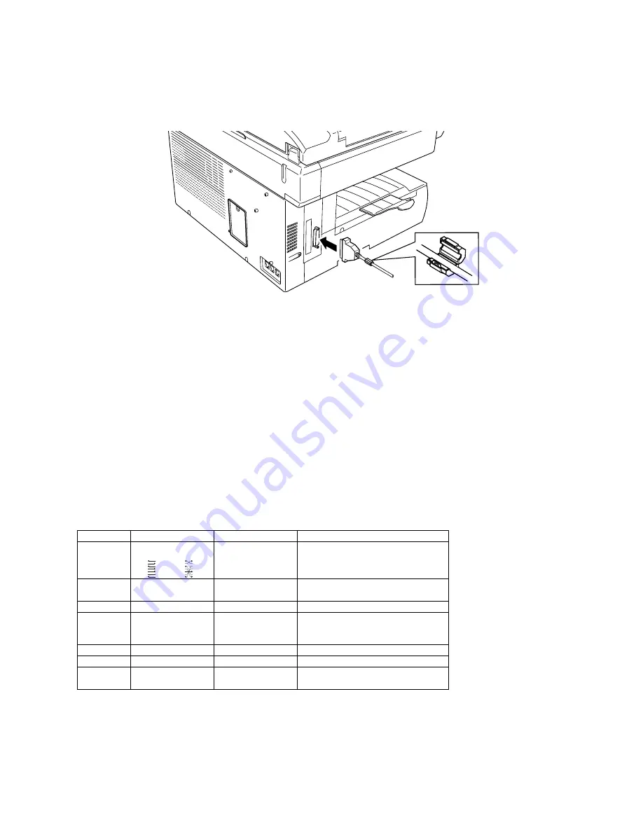
13. Attach the ferrite core to your RS-232C cable.
14. Connect one end of the RS-232C interface cable to the RS-232C interface port on your fax machine.
Note:
Please see next page for more details on the RS-232C cable.
15. Connect the other end of the RS-232C cable to your computer’s RS-232C port.
RS-232C interface cable
The RS-232C port on your newly installed RS-232C interface has a DB-25 (standard 25-pin serial) female
receptacle, which accepts a male DB-25 cable plug. Your computer’s port may have either a DB-25 or DB-
9 (9-pin) receptacle.
If necessary, see the chart below for detailed information on the pin assignment for your fax machine’s
RS232C port.
Note:
For more information on the computer’s serial interface port, see the computer’s operating
instructions.
Note:
Please use an RS-232C interface cable that is shorter than 3 meters.
Pin assignment
Pin No.
Signal code
Signal name
Contents
2
TXD
25-pin type
Your fax Your computer
2 TXD
2 TXD
3 RXD
3 RXD
4 RTS
4 RTS
5 CTS
5 CTS
6 DSR
6 DSR
7 SG
7 SG
20 DTR
20 DTR
9-pin type
Your fax Your computer
2 TXD
2 RXD
3 RXD
3 TXD
4 RTS
4 DTR
5 CTS
5 SG
6 DSR
6 DSR
7 SG
7 RTS
20 DTR
8 CTS
Transmitted data
Data signal sent from computer
to your fax.
3 RXD
Received
data
The data sent to computer by
your fax.
4
RTS
Request to send
Signal for request to send data.
5
CTS
Clear to send
Data Enable signal for data
transmission from your fax to
your computer.
6
DSR
DCE ready
Turning on always.
7
SG
Signal ground
Ground for signal.
20 DTR
DTE
ready
Data Terminal Enable – ready to
communicate
Содержание F-360
Страница 12: ...2 1 Section2 Machine Composition 2 1 F 360 Interconnect Block Diagram...
Страница 13: ...2 2...
Страница 14: ...2 3 F 320 Interconnect Block Diagram...
Страница 254: ...6 29 13 Attach the paper tray of the 2 Bin unit...


