vii
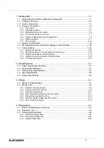
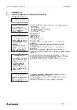
Introduction Procedure and Reference Manuals ................................................. 1-1
1.4.1 Part names ................................................................................................................ 1-4
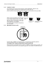
1.4.2 Installation method .................................................................................................... 1-5
1.4.3 MANU/AUTO selector switch .................................................................................... 1-5
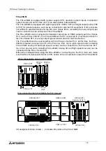
1.4.4 Connecting the PLC main unit................................................................................... 1-7
1.4.5 System configuration and I/O assignment................................................................. 1-8
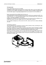
1.4.6 Status indication ...................................................................................................... 1-11
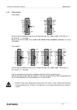
1.4.7 I/O connector ........................................................................................................... 1-12
Pin Assignment and Connection Diagram of Each Cable ................................. 1-18
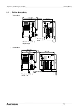
1.7.1 Outside dimensions ................................................................................................. 1-24
1.7.2 I/O specifications of terminal block (AC input type) ................................................. 1-25
1.7.3 Output specifications of terminal block .................................................................... 1-25
1.7.4 Internal connection diagram of terminal block ......................................................... 1-26
1.7.5 Terminal block layout .............................................................................................. 1-31
3.2.1 Example of wiring of input ......................................................................................... 3-5
3.2.2 Output connection example....................................................................................... 3-8
3.2.3 Operation input wiring ............................................................................................. 3-10
3.2.4 Drive system/mechanical system I/O wiring ............................................................ 3-11
3.2.5 Manual pulse generator wiring ................................................................................ 3-12
3.2.6 Absolute position (ABS) detection wiring ................................................................ 3-13
3.2.7 I/O connection example........................................................................................... 3-14
4.3.1 Positioning Parameters ............................................................................................. 4-8
4.3.2 I/O Control Parameters ........................................................................................... 4-23
4.3.3 System Parameters ................................................................................................. 4-32
Содержание FX2N-10GM
Страница 1: ...HARDWARE PROGRAMMING MANUAL FX2N 10GM FX2N 20GM ...
Страница 4: ...FX Series Positioning Controllers ii ...
Страница 6: ...FX Series Positioning Controllers iv ...
Страница 46: ...FX Series Positioning Controllers Introduction 1 1 34 MEMO ...
Страница 76: ...FX Series Positioning Controllers Wiring 3 3 24 MEMO ...
Страница 222: ...FX Series Positioning Controllers Operation Maintenance and Inspection 8 8 18 MEMO ...
Страница 256: ...FX Series Positioning Controllers Program Examples 9 9 34 MEMO ...

