FX Series Positioning Controllers
Operation, Maintenance and Inspection 8
8-10
Handling of DOG switch
The following four methods are available for the machine zero return operation depending on
the design of the DOG (width from the front end to the rear end) and the DOG switch.
1) Method used to avoid installation of a DOG switch (Operation example 1).
Forward and reverse travel can be executed in manual operation. When the system is
stopped, the present position can be set as the machine zero position by using push-button
commands.
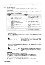
2) Method used when the DOG width must be as small as possible (Operation example 2).
In order to make it easier to adjust the point at which the DOG switch operates, the zero
return speed must be set as slow as possible.
If the zero return command is given at a position after the DOG has passed the DOG
switch, the machine first travels until the reverse limit switch is actuated, then travels forward
until the machine has passed the DOG switch, then travels in the reverse direction again to
return to the zero point.
This is called the DOG search function.
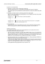
3) Method used when it is possible to set the DOG width greater than the motor deceleration to
creep distance (Operation example 3).
Deceleration is started when the front end of the DOG reaches the DOG switch, and the
zero point signal count is started when the rear end of the DOG reaches the DOG switch.
Since the zero point signal count starts after the creep speed has been attained, this
method makes adjustment of the DOG switch actuation point easier. The DOG search func-
tion is executed in the same way as described in 2).
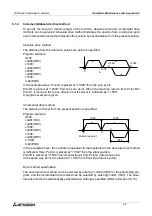
4) Method used when the DOG switch is a long way from the reverse limit switch and the DOG
search operation would take too long (Operation example 4).
If the DOG width is increased so that the DOG switch remains ON after completion of the
zero return operation, another zero return operation can be performed using this as a basis.
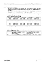
Operation example 1
When installation of a DOG switch must be avoided.
•
Set PARA 18 to "2 (mode without DOG)", and return the machine to the zero point manually.
•
Move the machine to the specified position using the FWD and RVS buttons. When the
machine is stopped, press the ZRN button.
•
Then, the CRL signal is issued and the deviation counter of the servo amplifier is cleared.
•
The zero point address set to PARA 16 is written in the present value register.
•
This operation need only be performed once when the absolute drive method is selected
using the MR-H/MR-J2/MR-J2-Super servo motor.
Содержание FX2N-10GM
Страница 1: ...HARDWARE PROGRAMMING MANUAL FX2N 10GM FX2N 20GM ...
Страница 4: ...FX Series Positioning Controllers ii ...
Страница 6: ...FX Series Positioning Controllers iv ...
Страница 46: ...FX Series Positioning Controllers Introduction 1 1 34 MEMO ...
Страница 76: ...FX Series Positioning Controllers Wiring 3 3 24 MEMO ...
Страница 222: ...FX Series Positioning Controllers Operation Maintenance and Inspection 8 8 18 MEMO ...
Страница 256: ...FX Series Positioning Controllers Program Examples 9 9 34 MEMO ...

