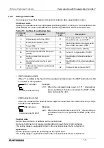
FX Series Positioning Controllers
Operation, Maintenance and Inspection 8
8-11
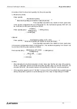
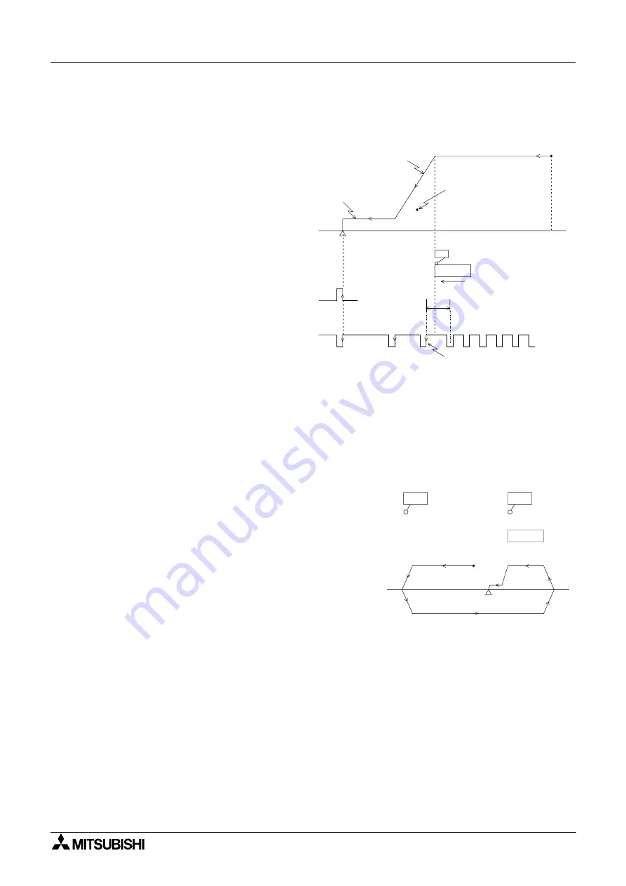
Operation example 2
When the DOG width must be as small as possible.
•
If the ZRN input is turned ON in the
MANU mode or the DRVZ instruction
is executed in the AUTO mode, a
machine zero return operation will be
executed.
•
The zero return speed, the zero
return direction, the deceleration time,
the creep speed, et c. are set by
parameters.
•
Deceleration is started when the front
end of the DOG reaches the DOG
switch, and the zero signal count is
started when either the front end or
the rear end of the DOG reaches the
DOG switch. (The setting of PARA 18
determines the start timing.)
•
When the PG0 count value reaches
the specified value (set to PARA 17),
travel is stopped, the clear signal
(CLR) is issued, and the zero point
address (set to PARA 16) is written to
the present value register.
Dog search function
•
If a zero return operation is executed when the
DOG has already passed the DOG switch and is
stopped, the machine first travels until the limit
switch is actuated and then reverses the direction
and executes the zero return operation again.
•
The limit switches and the DOG switch used can be
either the nor mally open type or the normally
closed type (The type can be set by parameters.).
•
If the limit switches LSR and LSF are not connected
to the positioning unit, the escape operation must
be performed manually.
PARA 9 :
Deceleration
time
PARA 13 : Zero return
speed
PARA 15 : Zero return direction
Initial
position
PARA 14 :
Creep speed
The number of zero
point signals set to
PARA 17 must allow for
the number of pulses
required for deceleration
distance.
PARA 16 :
Machine zero
point address
CLR :
Clear output
DOG
DOG switch
Front
end
Rear
end
PARA 18 :
Count start timing
PARA 19 :
DOG input logic
PG0 : Zero point signal
PARA 17 :
Number of zero
point signals
OFF
ON
Count is started
*
* Adjust to ensure that the DOG switch actuation point
is within the period between two consecutive PG0
pulses. In order to make adjustment easier, the zero
return speed must be made as low as possible.
Limit switch
LSF (LSR)
DOG switch
DOG
Initial position
Escape operation
Содержание FX2N-10GM
Страница 1: ...HARDWARE PROGRAMMING MANUAL FX2N 10GM FX2N 20GM ...
Страница 4: ...FX Series Positioning Controllers ii ...
Страница 6: ...FX Series Positioning Controllers iv ...
Страница 46: ...FX Series Positioning Controllers Introduction 1 1 34 MEMO ...
Страница 76: ...FX Series Positioning Controllers Wiring 3 3 24 MEMO ...
Страница 222: ...FX Series Positioning Controllers Operation Maintenance and Inspection 8 8 18 MEMO ...
Страница 256: ...FX Series Positioning Controllers Program Examples 9 9 34 MEMO ...

