FX Series Positioning Controllers
Wiring 3
3-14
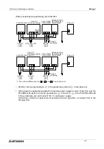
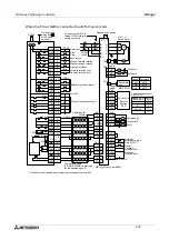
3.2.7
I/O connection example
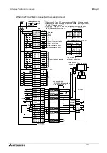
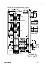
When the FX
2N
-10GM is connected to a stepping motor.
9,19
11
12
13
14
9,19
15
16
Y01
Y00
COM1
X03
X02
X01
X00
COM1
8
1
2
3
4
5
6
7
LSR
LSF
DOG
RVS
FWD
ZRN
STOP
START
COM1
3.3k
W
24+
24-
Y02
17
Y03
18
Y04
10
Max
50mA
CON1
5 to 24V
Y05
20
1
2
12
SVEND
11
COM4
14
PGO
COM
VIN
OH
CW+
FP
CW-
CCW+
RP
CCW-
ST1
10
ST2
20
4
150
W
9,19
3
CLR
15
*1
16
9.19
6
17,18
7, 8
5
13
5V
(*3)
2k
W
3.3k
W
DC24V
CON1
SVRDY
5V
5 to
24V
Home position
sensor *2
Connect
to
general
purpose
inputs.
CON2
(*3)
Do the ground wiring
with or FG of the
drive unit.
5 to 24V
Automatic
Start
Stop
Zero return
Manual forward rotation
Manual reverse rotation
Near-point signal
Forward rotation limit
Reverse rotation limit
Notes
Short-circuit STI and ST2 when connecting PG0 to a 5 V power supply.
When home position sensor is not provided, the zero point signal count
(PARA. 17) must be set to "0".
The wiring for the SVRDY and SVEND signals is not required when
PARA.22 is set to "1 (servo ready check invalid)" and PARA.21 is set
to "0 (servo end check invalid)".
3.3k
W
3.3k
W
3.3k
W
*1.
*2.
*3.
31
ZRN
X375
FWD
X376
X377
A
72 - x
B
72 - x
71 - x
RVS
Manual Automatic
Table: Assignment of
X00 to X03.
Enable
Manual pulse
generator
Interrupt
input
General purpose inputs
General purpose outputs
Cable length:
2m max.
The optional cable
(E-GM-200CAB) is provided
for the positioning unit.
Drive unit
Stepping motor
COM2
COM2
COM5
COM3
Содержание FX2N-10GM
Страница 1: ...HARDWARE PROGRAMMING MANUAL FX2N 10GM FX2N 20GM ...
Страница 4: ...FX Series Positioning Controllers ii ...
Страница 6: ...FX Series Positioning Controllers iv ...
Страница 46: ...FX Series Positioning Controllers Introduction 1 1 34 MEMO ...
Страница 76: ...FX Series Positioning Controllers Wiring 3 3 24 MEMO ...
Страница 222: ...FX Series Positioning Controllers Operation Maintenance and Inspection 8 8 18 MEMO ...
Страница 256: ...FX Series Positioning Controllers Program Examples 9 9 34 MEMO ...

