FX Series Positioning Controllers
Introduction 1
1-12
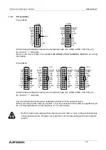
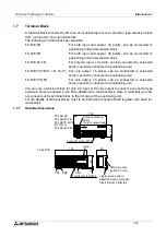
1.4.7
I/O connector
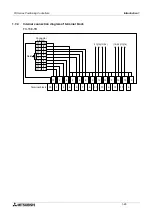
FX
2N
-10GM
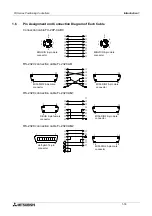
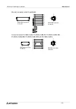
All terminals with identical names are shorted internally. (Ex. COM1-COM1, VIN-VIN, etc.)
Do not wire "
y
" terminals.
Refer to the FX
2N
-10GM, FX
2N
-20GM HARDWARE PROGRAMMING MANUAL for wiring
information.
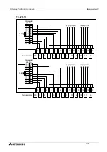
FX
2N
-20GM
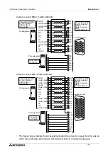
All terminals with identical names are shorted internally. (Ex. COM1-COM1, VIN-VIN, etc.)
Do not wire "
y
" terminals.
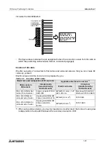
The pin assignment shown above indicates connectors of the positioning unit.
When you create an I/O cable by yourself, "
▲
" on the connector of the cable is regarded as pin
No. 20. Pay rigid attention to the positions of "
▲
" and notches.
•
Perform Class 3 grounding with an electric wire of 2 mm
2
or more to the ground terminal
in the positioning unit. However, never perform common grounding with a strong power
system.
CON1
X1
X0
X2
X3
Y0
Y1
Y2
Y3
COM1
COM2
SVRDY
CLR
COM3
FP
VIN
VIN
COM5
ST1
CON2
COM2
SVEND
PG0
COM4
RP
VIN
VIN
COM5
ST2
STOP
START
ZRN
FWD
RVS
DOG
LSF
LSR
COM1
Y4
Y5
Notch
Y00
Y01
Y02
Y03
Y04
Y05
Y06
Y07
COM1
CON1
X01
X00
X02
X03
X04
X05
X06
X07
COM1
STOP
START
ZRN
FWD
RVS
DOG
LSF
LSR
COM1
CON2
STOP
START
ZRN
FWD
RVS
DOG
LSF
LSR
COM1
COM2
SVRDY
CLR
COM3
FP
VIN
VIN
COM5
ST1
CON3
COM2
SVEND
PG0
COM4
RP
VIN
VIN
COM5
ST2
COM9
VIN
VIN
RP
COM8
PG0
SVEND
ST4
COM6
CON4
ST3
COM9
VIN
VIN
FP
COM7
CLR
SVRDY
COM6
(X axis)
(Y axis)
X axis
Y axis
Notch
Содержание FX2N-10GM
Страница 1: ...HARDWARE PROGRAMMING MANUAL FX2N 10GM FX2N 20GM ...
Страница 4: ...FX Series Positioning Controllers ii ...
Страница 6: ...FX Series Positioning Controllers iv ...
Страница 46: ...FX Series Positioning Controllers Introduction 1 1 34 MEMO ...
Страница 76: ...FX Series Positioning Controllers Wiring 3 3 24 MEMO ...
Страница 222: ...FX Series Positioning Controllers Operation Maintenance and Inspection 8 8 18 MEMO ...
Страница 256: ...FX Series Positioning Controllers Program Examples 9 9 34 MEMO ...


