FX Series Positioning Controllers
Operation, Maintenance and Inspection 8
8-7
8.2
Diversified Operations
In order to safely use the positioning unit, you should know available control.
This paragraph describes operations realized by the positioning unit.
8.2.1
Zero return
The positioning unit incorporates a present value register in order to record the absolute posi-
tion. This is incremented and decremented in accordance with the forward rotation and reverse
rotation pulses that it itself generates. This means that the machine position is always known.
The present position of the machine must be taught by writing it to this register when operation
is started for the first time.
Because the present value register is cleared when the power is turned OFF, the machine zero
return operation must always be executed after turning the power ON.
* Note that this does not apply if an MR-H, MR-J2 or MR-J2-Super servo motor is used
because such a motor has a function for counting pulses after the power is turned OFF and a
function for retaining the present value, which means that the zero return operation need only
be performed once. (Refer to Section 4.3.2.)
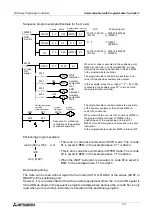
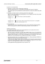
The machine zero return operation is performed as follows.
1) The machine zero return command is given.
2) The machine travels toward the machine zero return direction specified by PARA 15 at the
zero return speed specified by PARA 13.
3) When the near-point signal (DOG) is turned ON, the machine decelerates to the creep
speed specified by PARA 14.
4) When the zero point signals are counted to the number specified by PARA 17 (after the
near-point signal is turned ON), the machine is stopped and the machine zero return opera-
tion is completed.
Switch that is
turned OFF at
the reverse limit
Motor
Near-point signsl
DOG
LSR
Switch that is turned ON
before the zero point is
reached
Front end
LSF
Dog
Rear end
Switch that is
turned OFF at
the forward
linit
Reverse
Forward
Creep
speed
This is the
zero point.
Initial position
Zero return speed
Zero point
signal
PG0
The DOG switch must
be turned ON or OFF
within the period between
two consecutibe PG0
pulses.
The number of zero point signal pulses (PG0) sent from the drive
unit to the positioning unit is counted and operation is stopped when
this number reaches the specified value.
Usually, one zero point pulse is generated per rotation of the motor.
Содержание FX2N-10GM
Страница 1: ...HARDWARE PROGRAMMING MANUAL FX2N 10GM FX2N 20GM ...
Страница 4: ...FX Series Positioning Controllers ii ...
Страница 6: ...FX Series Positioning Controllers iv ...
Страница 46: ...FX Series Positioning Controllers Introduction 1 1 34 MEMO ...
Страница 76: ...FX Series Positioning Controllers Wiring 3 3 24 MEMO ...
Страница 222: ...FX Series Positioning Controllers Operation Maintenance and Inspection 8 8 18 MEMO ...
Страница 256: ...FX Series Positioning Controllers Program Examples 9 9 34 MEMO ...

