


Graphic Operation Terminal F930GOT
Introduction 1
1-22
-
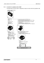
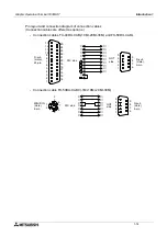
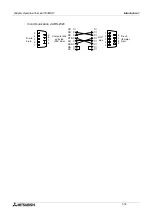
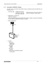
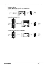
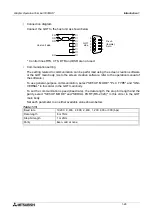
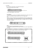
Setting of switches on rear face (C200H-LK201-V1)
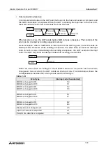
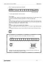
(C200H-LK202-V1)
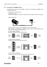
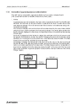
•
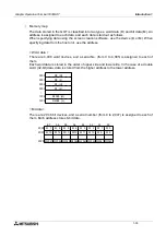
Cautions
Operation mode of the SYSMAC C Series
When changing the current value and the set value of each device in the C Series PLC, the
PLC should be set to the monitor mode.
If the GOT is connected and the C Series PLC is started up in the running mode, the GOT
automatically sets the PLC to the monitor mode so that the data can be changed.
-
Forced setting to ON/OFF in the HPP mode (GOT function)
In the HPP mode of the GOT, the forced ON/OFF function is available. This function is
available also when the C Series PLC is connected as the host unit.
However, have in mind that the forced ON/OFF function offers the following operation in
the C Series PLC.
* The forced setting/resetting function in the C Series PLC holds the current ON/OFF sta-
tus without regard to a sequence program.
The forced ON/OFF function described here sets a specified bit to ON/OFF. If a
sequence program gives an ON/OFF command after that, the status of the specified bit
device which has been forcedly set to ON/OFF is changed.
Forced ON : Data "1" is specified. (The specified bit is set to ON.)
Forced OFF : Data "0" is specified. (The specified bit is set to OFF.)
•
Restriction in functions
When a host link unit is connected, the following GOT functions are disabled or restricted.
-
Because the GOT switch function (which sets a bit to ON/OFF) uses a host link com-
mand, FK command (which sets/resets multi-points forcedly), the switch function is not
available in models which do not support the FK command.
-
The set value of timers (T) and counters (C) cannot be monitored nor changed.
-
When the RS-232C is connected for communication, the printer output function of the
GOT is disabled.
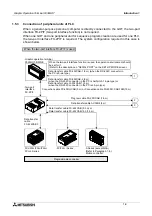
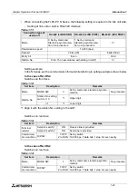
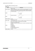
Table 1.8:
Set item
Switch setting
Remarks
Procedure
DTP.SW No.3
ON
1:N procedure
5 V power supply
DTP.SW No.4
OFF
5 V is not supplied.
CTS changeover
Selector switch Upper side External
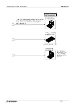
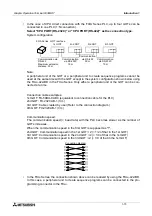
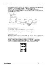
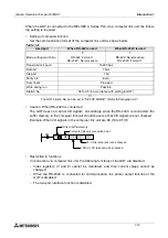
Table 1.9:
Set item
Switch setting
Remarks
Procedure
Right selector switch
Lower side 1:N procedure
Connection of terminal resistor
Left selector switch
Upper side Provided
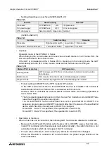
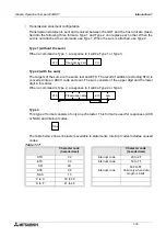
Table 1.10:
Mode of PLC at startup
GOT operation
Running mode
GOT changes over PLC from running mode to monitor mode to enable
data change.
Monitor mode
PLC remains in monitor mode, and data change is enabled.
Program mode
PLC remains in program mode, and data change is enabled.
Содержание F930GOT-BWD-E
Страница 1: ...USER S MANUAL F930GOT BWD E ...
Страница 4: ...Graphic Operation Terminal F930GOT ii ...
Страница 6: ...Graphic Operation Terminal F930GOT iv ...
Страница 14: ...vi ...
Страница 60: ...Graphic Operation Terminal F930GOT Start up 2 2 10 MEMO ...
Страница 68: ...Graphic Operation Terminal F930GOT Screen Mode 3 3 8 MEMO ...
Страница 120: ...Graphic Operation Terminal F930GOT Creation of Display Screens 8 8 30 ...
Страница 200: ...Graphic Operation Terminal F930GOT Changeover of Display Screen FX PCS DU WIN E 10 10 18 ...
Страница 272: ...Graphic Operation Terminal F930GOT Additional Functions in V 2 00 or later 13 13 24 MEMO ...


